Holographic waveguide display device of high diffraction efficiency and grating coupling method of holographic waveguide display device

A technology of diffraction efficiency and holographic waveguide, which is applied in the field of wearable display, can solve the problems of the upper limit of refractive index modulation and the inability to enter the human eye for imaging, and achieve the improvement of light energy utilization, high-efficiency holographic waveguide display, and improvement of diffraction efficiency. Effect

Active Publication Date: 2018-07-06
SOUTHEAST UNIV
View PDF4 Cites 19 Cited by
  • Summary
  • Abstract
  • Description
  • Claims
  • Application Information

AI Technical Summary

Problems solved by technology

Although dichromate gelatin (DCG) can meet the requirements of large refractive index modulation materials for volume holographic gratings, its refractive index modulation degree also has an upper limit, and when the grating is fabricated,

Method used


Image

  • Holographic waveguide display device of high diffraction efficiency and grating coupling method of holographic waveguide display device
  • Holographic waveguide display device of high diffraction efficiency and grating coupling method of holographic waveguide display device
  • Holographic waveguide display device of high diffraction efficiency and grating coupling method of holographic waveguide display device

Examples


Embodiment 1

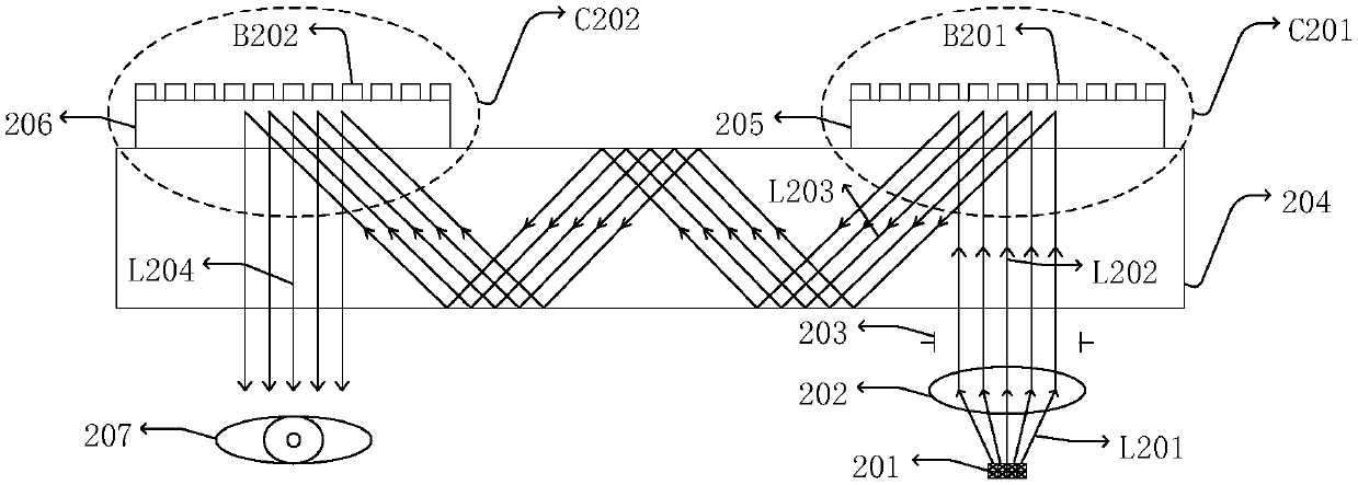
[0064] An embodiment of a holographic waveguide display device, the structure of which is as follows figure 2 shown. The grating structure parameters are: the thickness of the in-coupling reflective volume holographic grating 205 is 10 μm, the Bragg wavelength is 525 nm, the grating tilt angle is 26°, the in-coupling one-dimensional wavelength binary grating is metal silver grating, the thickness is 80 nm, and the period is 480 nm. The fill factor is 0.5. The in-coupling one-Via-wavelength binary grating B201 is arranged from the leftmost position of the volume holographic grating 205, and the relative position of the reflective volume holographic grating 205 and the one-Via-wavelength binary grating B201 is Δx=200nm.

[0065] The thickness of the outcoupling reflective volume holographic grating 206 is 10 μm, the Bragg wavelength is 525nm, and the tilt angle of the grating is -26°. The outcoupling one-dimensional wavelength binary grating B202 is a metal silver grating with...

Embodiment 2

[0069] An embodiment of a holographic waveguide display device, the structure of which is as follows figure 2 shown. The grating structure parameters are: the in-coupling reflective volume holographic grating 205 has a thickness of 10 μm, the Bragg wavelength is 525 nm, and the grating tilt angle is 26°; the in-coupling one-dimensional wavelength binary grating is metallic silver grating with a thickness of 80 nm and a period of 480 nm. The fill factor is 0.5. The in-coupling one-Via wavelength binary grating B201 is arranged from the leftmost position of the volume holographic grating 205, and the relative position of the reflective volume holographic grating 205 and the one-Via wavelength binary grating B201 is Δx=200nm.

[0070]The thickness of the outcoupling reflective volume holographic grating 206 is 10 μm, the Bragg wavelength is 525nm, and the tilt angle of the grating is -26°. The outcoupling one-dimensional wavelength binary grating B202 is a dielectric grating wi...

Embodiment 3

[0074] An embodiment of a holographic waveguide display device, the structure of which is as follows figure 2 shown. The grating structure parameters are: the in-coupling reflective volume holographic grating 205 is a composite color volume holographic grating, and the refractive index of the composite volume holographic grating is the superposition of the average refractive index and multiple refractive index modulation degrees,
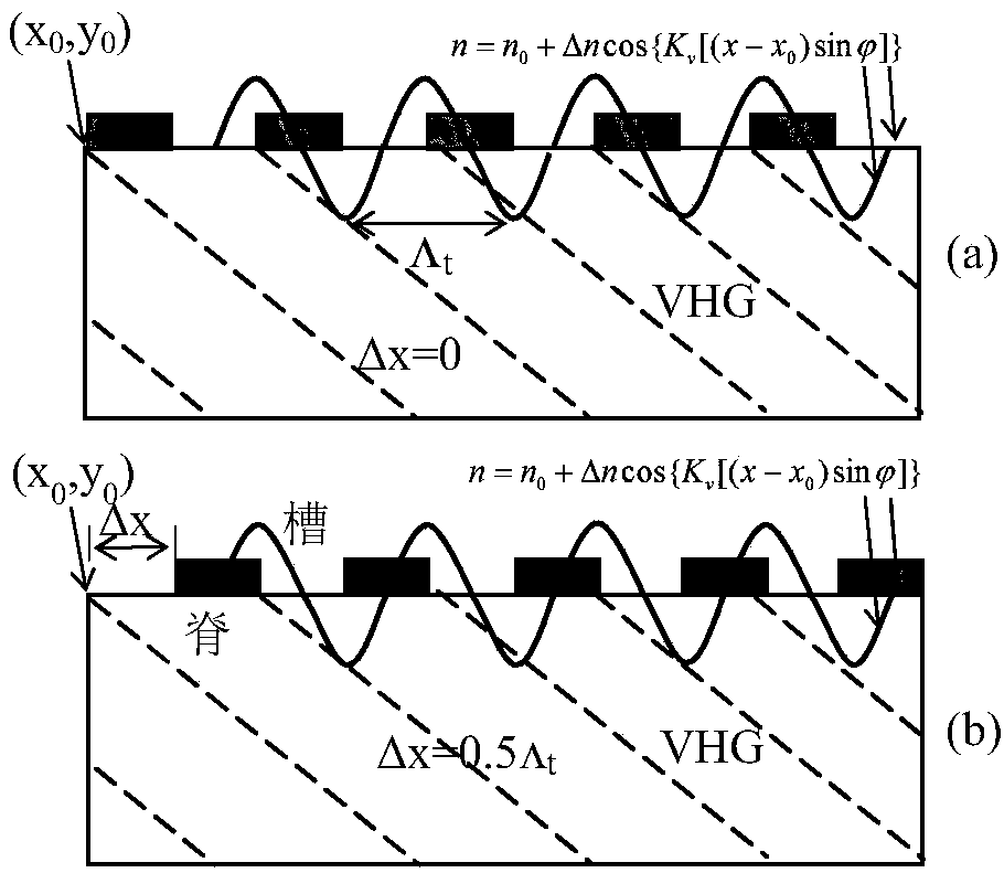
[0075]

[0076] Among them, n 0 is the average refractive index of the material, Δn is the refractive index modulation degree, K is the grating vector, which can be obtained by K=2π / Λ, Λ is the grating period, is the inclination angle. The subscripts of Δn and K represent different wavelengths.

[0077] In this example, n 0 =1.52,Δn=0.03, The wavelengths of the incident red, green and blue light are λ R =640nm,λ G =525nm,λ B =440nm, at this time, the x-direction components of the composite volume holographic grating corresponding to th...


PUM

PropertyMeasurementUnit
Thicknessaaaaaaaaaa
Thicknessaaaaaaaaaa
Thicknessaaaaaaaaaa

Abstract

The invention discloses a holographic waveguide display device of a high diffraction efficiency and a grating coupling method of the holographic waveguide display device. The holographic waveguide display device comprises a micro display (201), a collimating lens (202), a diaphragm (203), a waveguide (204), a coupling-in grating group (C201) and a coupling-out grating group (C202); the micro display (201) is positioned under the lower surface of the waveguide (204); and the coupling-in grating group (C201) and the coupling-out grating group (C202) are tightly connected with the right and leftends of the upper surface of the waveguide (204) respectively. According to the holographic waveguide display device, a 1D sub-wavelength binary grating is coupled to a reflective body holographic grating, the diffraction energy level can be re-distributed under the condition that wave vector matching and position matching are ensured, the diffraction efficiency in the main diffraction direction reaches the maximum, energy of a light beam diffracted into the eyes is maximal, and high-efficiency holographic waveguide display is realized.

Description

technical field [0001] The invention belongs to the technical field of wearable displays, and in particular relates to a holographic waveguide display device with high diffraction efficiency, in particular to a matched-coupled entrance and exit grating group. Background technique [0002] In the prior art, volume holographic gratings are mostly used as high-efficiency diffractive optical elements in holographic waveguide display devices, but the diffraction efficiency of volume holographic gratings is closely related to the grating manufacturing process. diffraction efficiency. Although dichromate gelatin (DCG) can meet the requirements of large refractive index modulation materials for volume holographic gratings, its refractive index modulation degree also has an upper limit, and when the grating is manufactured, the modulation degree of the actual exposed volume holographic grating is in the direction of thickness increase. It will also be reduced, so some energy still p...

Claims


Application Information

Patent Timeline
IPC IPC(8): G02B27/01G02B27/22G02B6/34
CPCG02B6/34G02B27/0101G02B30/27
Inventor 杨兰兰石在耀屠彦郭静菁王莉莉张宇宁张瑞文王垒
Owner SOUTHEAST UNIV
Why Eureka
Try Eureka