Seepage eliminating system for lowering tailing pond dam body seepage line by using mining barren rocks and construction method thereof

A technology for mining waste rocks and tailings ponds, applied in the field of seepage drainage systems, can solve the problems of large vertical sandbag wells, frequent fluctuations in the soaking line, and endangering the safety of the dam body, so as to be beneficial to environmental protection and improve the ability to resist liquefaction , The effect of accelerating drainage consolidation

Inactive Publication Date: 2018-07-10
NANHUA UNIV
View PDF5 Cites 9 Cited by
  • Summary
  • Abstract
  • Description
  • Claims
  • Application Information

AI Technical Summary

Problems solved by technology

Shafts are implemented when tailings are accumulated in sub-dams. Shafts are generally only suitable for thicker mud interlayers, and most of them require specialized personnel to manage them. Water that seeps into the wells needs to be sucked by water pumps, which consumes electricity and is prone to deformation in the later stage of dam accumulation.
Siphon wells are frequently cut off and require frequent manual treatment; light well points and radiation wells need to be pumped with water, the infiltration line fluctuates frequently, and the input cost is high, and in the later stage of construction, the well position is often inclined; Large, one-time investment costs are high; the construction process of laying the combined seepage drainage pipeline is relatively complicated, because most of the previous seepage drainage measures were constructed during the dam building process, which increased the difficulty of construction
For the three-phase combined seepage drainage system, since it is necessary to use vertical drainage wells to divert the water in different layers out of the dam slope, it is necessary to set up horizontal seepage drainage pipes or drainage holes in each layer, which is the key factor for the entire drainage system. The key link in the construction of the seepage system must be strictly controlled. If there is a problem in the construction of the horizontal seepage drainage process, it will inevitably affect the final seepage drainage effect, and in serious cases, it will endanger the safety of the dam body
Therefore, the combined seepage drainage method is only applicable to dams with disordered tailings drawing, more mud interlayers in accumulation dams, and obvious water-resisting layers.

Method used


Image

  • Seepage eliminating system for lowering tailing pond dam body seepage line by using mining barren rocks and construction method thereof
  • Seepage eliminating system for lowering tailing pond dam body seepage line by using mining barren rocks and construction method thereof
  • Seepage eliminating system for lowering tailing pond dam body seepage line by using mining barren rocks and construction method thereof

Examples


Embodiment 1

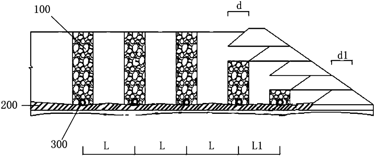
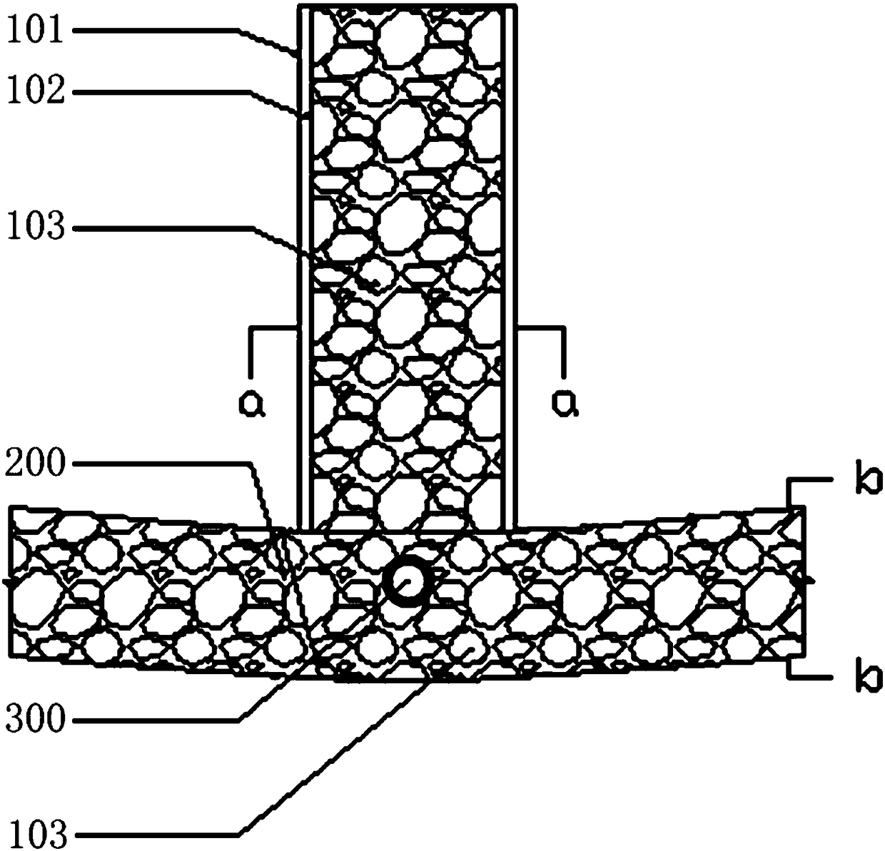
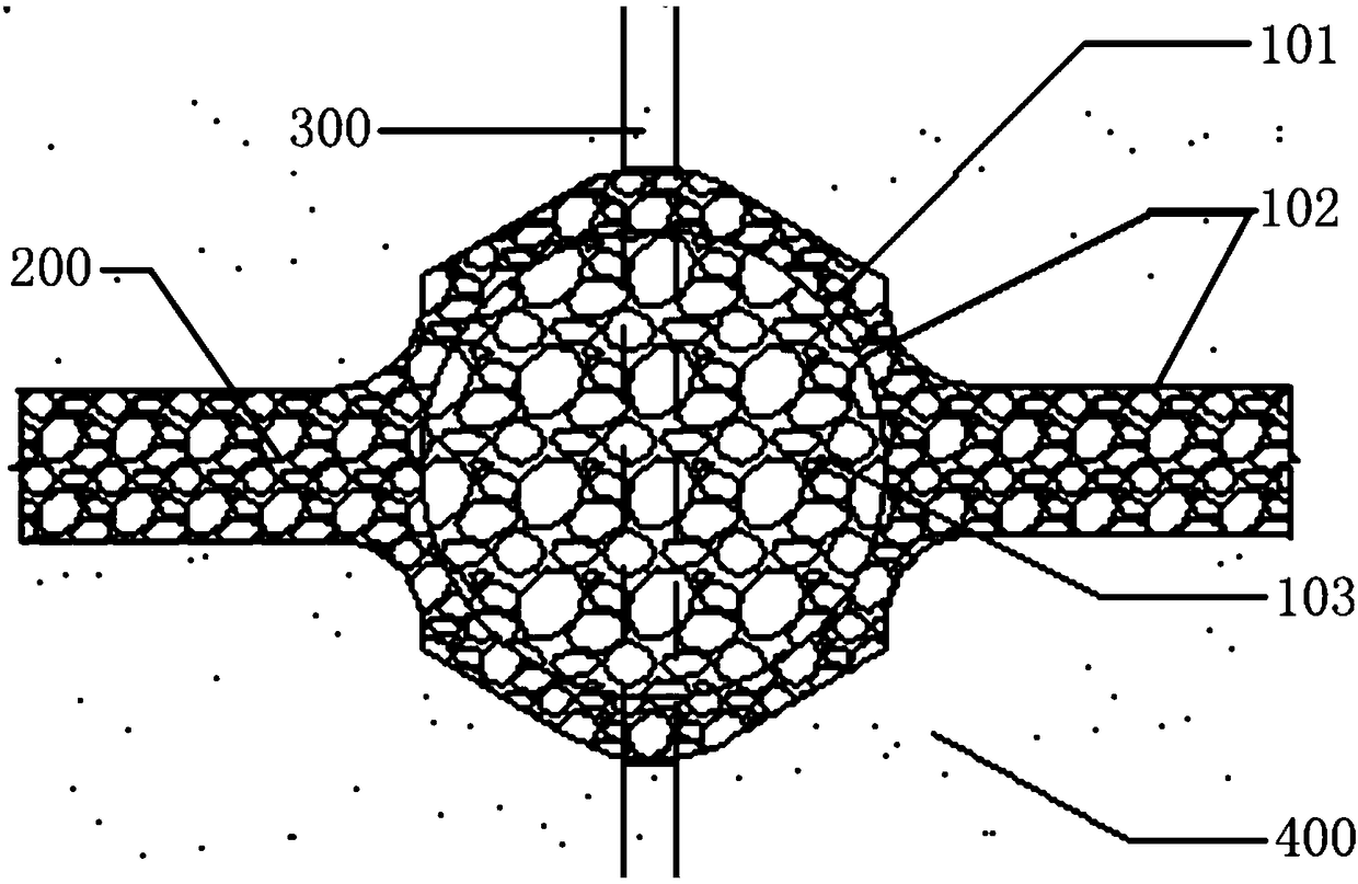
[0047] Such as figure 1 As shown, a seepage drainage system that uses mining waste rocks to reduce the wetting line of the dam body of the tailings pond provided by Embodiment 1 of the present invention includes: a waste rock column 100 arranged inside the dam body along the direction of the central axis of the dam; The horizontal seepage drainage blind ditch 200 arranged on the tailing sand deposition beach inside the dam body and the vertical seepage drainage pipe 300 arranged inside the dam body perpendicular to the direction of the central axis of the dam; Both are connected with the bottom of the waste stone column 100; the vertical seepage drainage pipe 300 is vertically intersected with the horizontal seepage drainage blind ditch 200; figure 2 As shown), the diameter d of the waste rock column is greater than or equal to the width d1 of the initial dam crest of the tailings pond, and the height of the waste rock column is not lower than the highest water level in the d...

Embodiment 2

[0053] Figure 5 It shows the steps of a seepage drainage construction method using mining waste rocks to reduce the wetting line of the tailings pond dam body provided by Embodiment 2 of the present invention, including: Step S1: According to the geological survey report and the foundation design data of the tailings pond, obtain Tailings dam basic information;

[0054] Wherein, the tailings dam basic information includes at least the width of the initial dam crest of the tailings pond, the direction of the central axis of the dam, the highest water level in the dam, and the height of the tailings dam;

[0055] Step S2: use mining waste rocks in the dam body to build waste stone pillars along the central axis of the dam;

[0056] Among them, the waste rock column includes skeleton, geotextile and mining waste rock arranged from outside to inside, the diameter of the waste rock column is greater than or equal to the width of the initial dam crest of the tailings pond, and the...


PUM


Abstract

The invention provides a seepage eliminating system for lowering a tailing pond dam body seepage line by using mining barren rocks and a construction method thereof. The seepage eliminating system comprises barren rock columns arranged in a dam body along a dam central axis, transverse seepage eliminating blind grooves arranged on a tailing sand deposition surface in the dam body along the dam central axis, and longitudinal seepage eliminating pipes arranged in the dam body perpendicular to the dam central axis. The barren rocks without economical value are used for producing the barrel rock columns to cooperate with the transverse seepage eliminating blind grooves and the longitudinal seepage eliminating pipes to form the seepage eliminating system capable of realizing self-flowing. The mining barren rocks are excellent in seepage performance, so that the seepage speed of seepage water in a tailing dam can be accelerated, the liquefication resistance of the tailing dam is improved, and the liquefication area of the dam body is reduced; the seepage eliminating system is low in cost, convenient to construct and popularize and higher in commercial value; and meanwhile, through limitations of specification parameters and arrangement modes of the barren rock columns, the drainage solidification of tailing sand can be accelerated, and the stability of a tailing pond can be improved.

Description

technical field [0001] The invention relates to the technical field of tailings dam body drainage, in particular to a seepage drainage system and a construction method for reducing the infiltration line of a tailings dam body by using mining waste rocks. Background technique [0002] As the lifeline of the tailings pond, the seepage line plays an important role in measuring the stability of the tailings pond dam. In my country's mining projects, due to the elevation of the soaking line inside the dam body, seepage water overflows from the dam body, forming swamps on the dam surface, causing piping, and endangering the stability of the dam body. Since 2005, there have been more than 40 tailings dam failures in my country. Some scholars have conducted statistics on more than 3,000 tailings dams around the world and found that on average, 2-5 tailings dams collapse every year. dam. In particular, the "9.8" tailings pond accident, which is known as the largest in the world so f...

Claims


Application Information

Patent Timeline
IPC IPC(8): E02B11/00E02D19/10
CPCE02B11/00E02D19/10
Inventor 贺桂成戴兵高羚翔廖家海
Owner NANHUA UNIV
Why Eureka
Try Eureka