Hybrid printed circuit board

A printed circuit board, microwave integrated circuit technology, applied in the direction of printed circuit, printed circuit, printed circuit components, etc., can solve the problems of optimizing radio frequency/microwave performance, etc., to achieve increased functional complexity, improved radio frequency performance, and good working bandwidth Effect

Pending Publication Date: 2018-07-10
ALUKSEN OPTOELECTRONICS CO LTD
View PDF0 Cites 2 Cited by
  • Summary
  • Abstract
  • Description
  • Claims
  • Application Information

AI Technical Summary

Problems solved by technology

The height of this cavity is limited to about 60 μm in the raised contact, makin

Method used


Image

  • Hybrid printed circuit board
  • Hybrid printed circuit board
  • Hybrid printed circuit board

Examples


Example Embodiment

[0030] The embodiments of the present invention are described in detail below. Examples of the embodiments are shown in the accompanying drawings, in which the same or similar reference numerals indicate the same or similar elements or elements with the same or similar functions. The embodiments described below with reference to the accompanying drawings are exemplary, and are intended to explain the present invention, but should not be construed as limiting the present invention.

[0031] In the description of the present invention, it should be understood that the terms "length", "width", "upper", "lower", "front", "rear", "left", "right", "vertical", The orientation or positional relationship indicated by "horizontal", "top", "bottom", "inner", "outer", etc. is based on the orientation or positional relationship shown in the drawings, and is only for the convenience of describing the present invention and simplifying the description. It does not indicate or imply that the poin...


PUM


Abstract

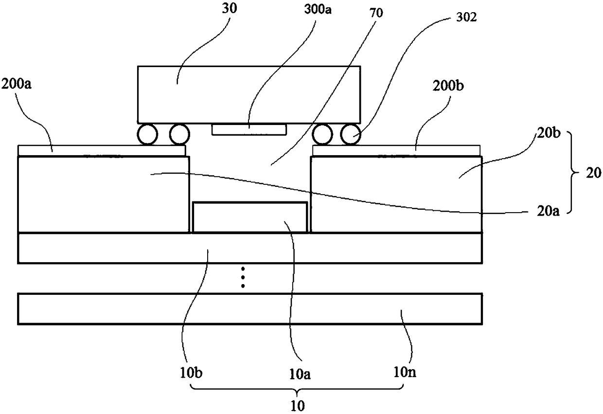
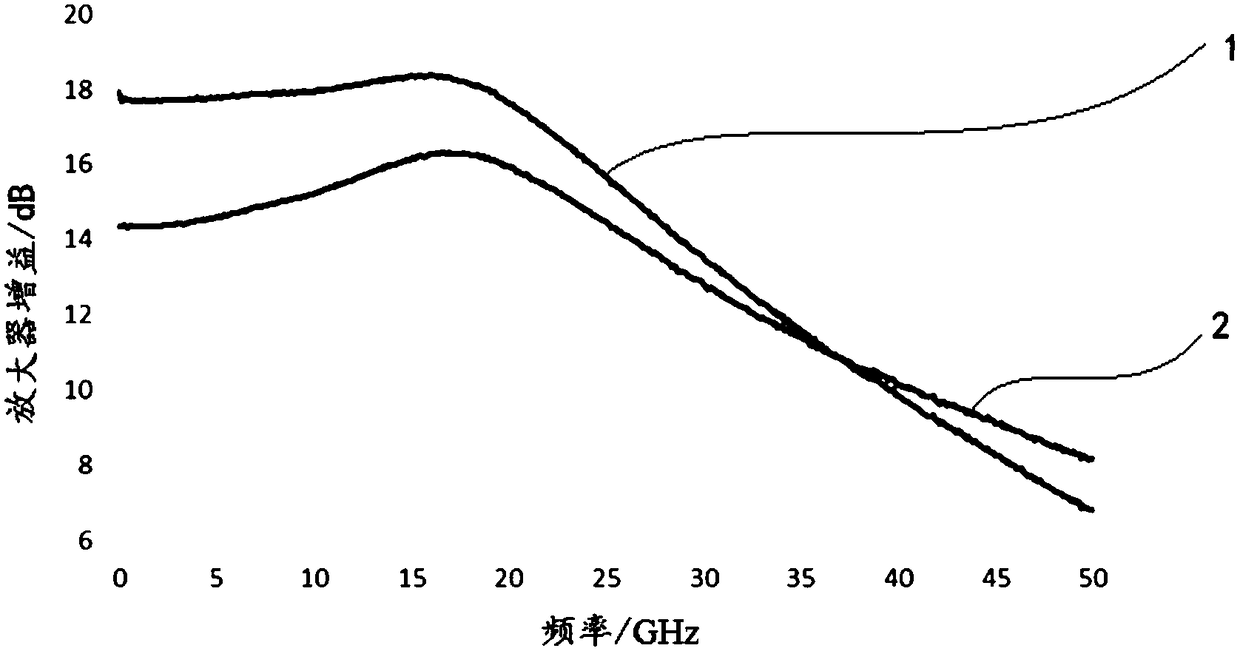
The invention discloses a hybrid printed circuit board, and the printed circuit board comprises a low frequency substrate, a high frequency substrate, and an MMIC (monolithic microwave integrated circuit) die, wherein the MMIC die is disposed on the high frequency substrate in an inverted manner. The low frequency substrate includes a first low frequency substrate and a second low frequency substrate, and the high frequency substrate includes a first high frequency substrate and a second high frequency substrate. The first high frequency substrate and the second high frequency substrate are spaced apart from each other and laminated on a surface of the second low frequency substrate. The first low frequency substrate is laminated on the surface of the second low frequency substrate and islocated between the first high frequency substrate and the second high frequency substrate. The first high frequency substrate, the second high frequency substrate, the inverted MMIC die and the firstlow frequency substrate define a cavity jointly. The printed circuit board can effectively reduce the stray inductance, obtains the better work bandwidth, and improves the radio frequency performances of a system.

Description

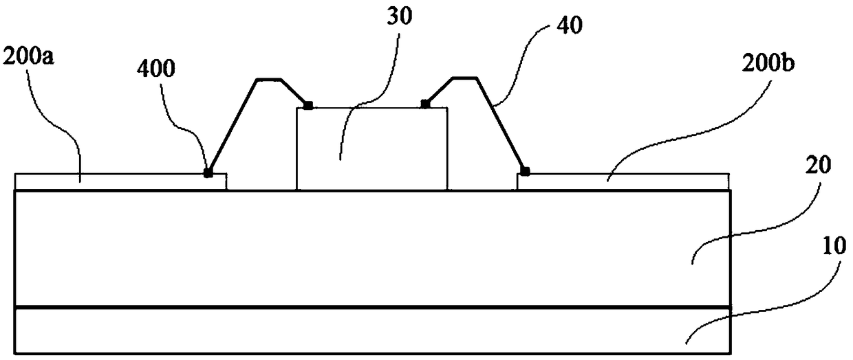
technical field [0001] The present invention relates to the technical field of integrated circuits, and more specifically, the present invention relates to a hybrid printed circuit board for chip flipping. Background technique [0002] At present, in the field of integrated circuit technology, traditional chip module packaging is composed of multiple discrete integrated circuits (IC, Integrated Circuits) and multiple active and passive electronic components. The disadvantages of using these traditional methods are large size, high power consumption, and long signal lines. With the continuous increase of operating frequency, it has become a serious problem that restricts the improvement of module performance. Unlike traditional systems that use multiple discrete integrated circuits and multiple active and passive electronic components, multi-chip module (MCM, Multi-Chip Module) packaging technology has gained considerable development in recent years due to overcoming the defe...

Claims


Application Information

Patent Timeline
IPC IPC(8): H01L23/66H01L25/16H05K1/02H05K1/18
CPCH01L2224/16225H01L2224/48227H01L25/16H01L23/66H01L2223/6644H01L2223/6683H05K1/0237H05K1/181H05K2201/10674
Inventor 袁亚兴商松泉
Owner ALUKSEN OPTOELECTRONICS CO LTD
Why Eureka
Try Eureka