Motor control device of intelligent terminal and intelligent terminal

A motor control and intelligent terminal technology, applied in control systems, motor control, AC motor control, etc., can solve the problems of vibration consumption, excessive power consumption, affecting the endurance of intelligent terminals, etc., to achieve a simple structure, small footprint, and reduced impact. Effect

Inactive Publication Date: 2018-07-10
SHANGHAI MORUAN COMM TECH
View PDF4 Cites 2 Cited by
  • Summary
  • Abstract
  • Description
  • Claims
  • Application Information

AI Technical Summary

Problems solved by technology

[0003] The technical problem to be solved by the present invention is to overcome the defect that the internal motor of the smart terminal generally vibrates at a constant voltage or constant voltage in the prior art. Such vibration consumes more power and affects the battery life of the smart terminal, and provides a smart terminal motor control device and intelligent terminal

Method used


Image

  • Motor control device of intelligent terminal and intelligent terminal
  • Motor control device of intelligent terminal and intelligent terminal
  • Motor control device of intelligent terminal and intelligent terminal

Examples


Embodiment 1

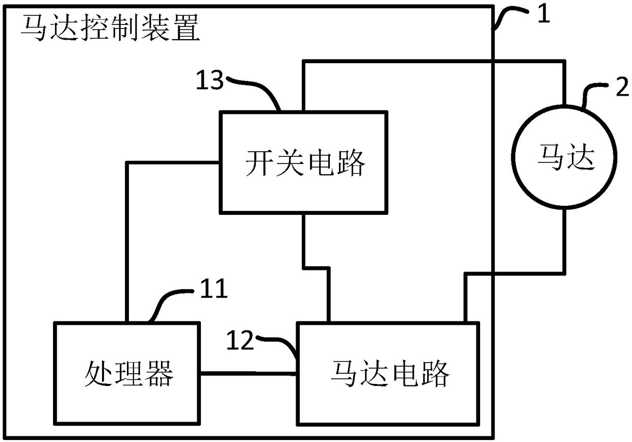
[0027] like figure 1 As shown, in the motor control device of the smart terminal involved in this embodiment, the motor control device 1 includes a processor 11 and a motor circuit 12, the processor 11 is electrically connected to the motor circuit 12, and the motor control device 1 further includes a switch circuit 13. The switch circuit 13 is electrically connected to the processor 11, the motor circuit 12 is electrically connected to the motor 2 through the switch circuit 13, the processor 11 is used to control the motor circuit 12 to drive the motor 2 to vibrate, and the processor 11 is also used to generate a switch control signal , the switch control signal is used to control the on-off of the switch circuit 13. When the switch control signal is at a high level, the switch circuit 13 is in an on state; when the switch control signal is at a low level, the switch circuit 13 is in an open circuit state.

[0028] In this embodiment, by adding the switch circuit 13, the sig...

Embodiment 2

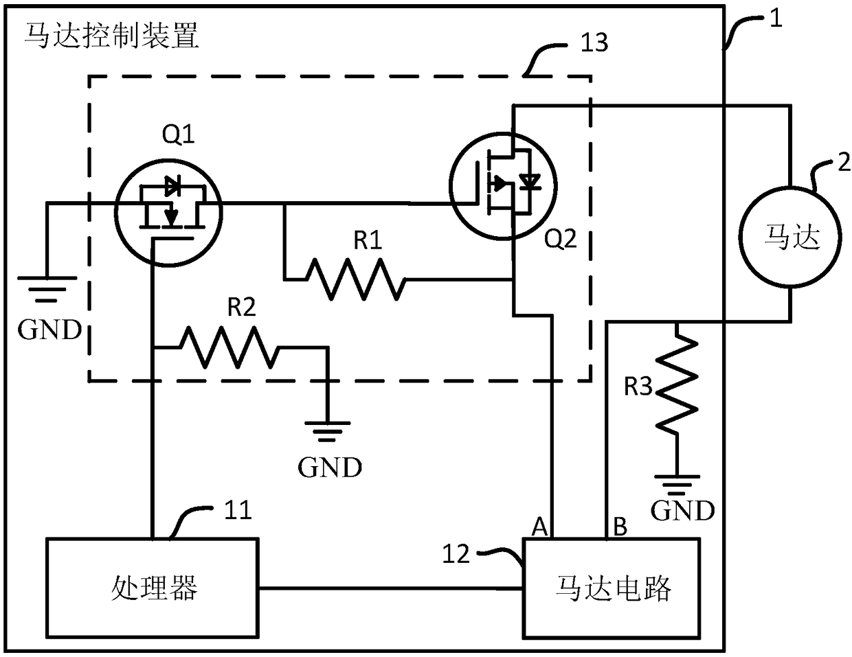
[0030] The motor control device of the smart terminal involved in this embodiment provides a possible implementation of the motor control device 1 and its switch circuit 13 on the basis of the first embodiment, such as figure 2 As shown, the switch circuit 13 includes a first MOS power transistor Q1, a second MOS power transistor Q2 and a first resistor R1. The gate of the first MOS power transistor Q1 is electrically connected to the processor 11, and the source of the first MOS power transistor Q1 is electrically connected to the processor 11. The electrode is connected to the signal ground GND, the drain of the first MOS power transistor Q1 is connected to the gate of the second MOS power transistor Q2, the source of the second MOS power transistor Q2 is connected to the output positive terminal A of the motor circuit 12, the second The drain of the MOS power transistor Q2 is connected to one end of the motor 2, the other end of the motor 2 is connected to the output negati...

Embodiment 3

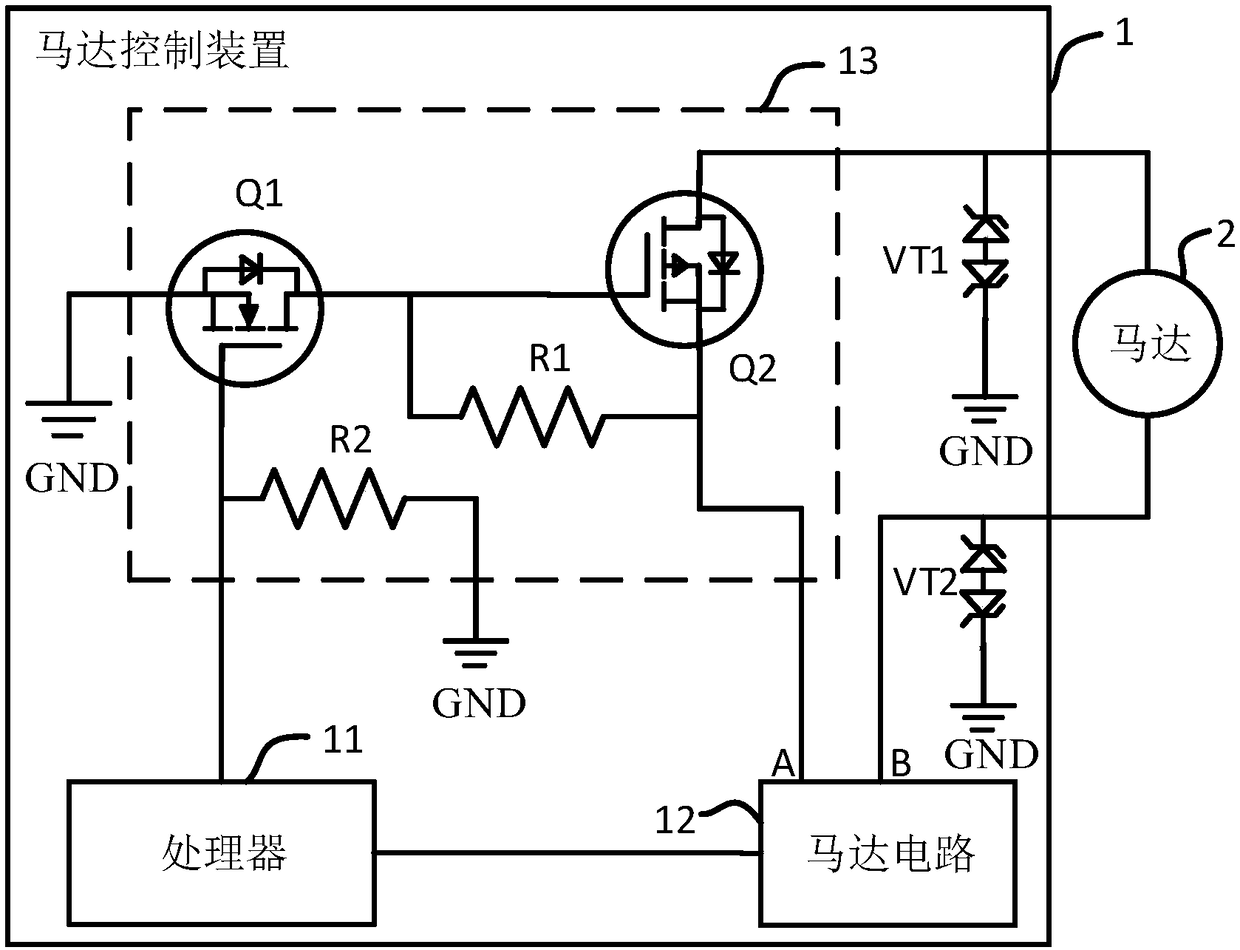
[0035] The motor control device of the smart terminal involved in this embodiment provides a possible implementation of the motor control device 1 on the basis of the second embodiment, such as image 3As shown, the third resistor R3 may not be needed, and then the first electrostatic diode VT1 is connected between one end of the motor 2 and the signal ground GND, and the second electrostatic diode VT2 is connected between the other end of the motor 2 and the signal ground GND, Achieve better electrostatic protection. Specifically, the motor control device 1 further includes a first electrostatic diode VT1 and a second electrostatic diode VT2, one end of the first electrostatic diode VT1 is connected to one end of the motor 2, and the other end of the first electrostatic diode VT1 is connected to the signal ground GND; One end of the two electrostatic diodes VT2 is connected to the other end of the motor 2, and the other end of the second electrostatic diode VT2 is connected t...


PUM


Abstract

The invention discloses a motor control device of an intelligent terminal and an intelligent terminal. The motor control device comprises a processor and a motor circuit. The processor is electricallyconnected with the motor circuit. The processor is used for controlling the motor circuit to drive a motor to vibrate. The motor control device further includes a switch circuit. The switch circuit is electrically connected with the processor. The motor circuit is electrically connected with the motor through the switch circuit. The processor is further used for generating a switch control signal. The switch control signal is used for controlling the on/off of the switch circuit. When the switch control signal is high in level, the switch circuit is in an on state, and when the switch controlsignal is low in level, the switch circuit is in an off state. According to the invention, by only adding the switch circuit and combining the switch control signal to control the on and off of the switch circuit, the intermittent driving of the motor is realized, the problem that the long vibration or the constant voltage vibration of the motor consumes a lot of electric energy is well solved, the circuit is simple, the cost is low, the power consumption is low and the size is small, and the requirements of the intelligent terminal can be well met.

Description

technical field [0001] The invention relates to the field of motor control, in particular to a motor control device of an intelligent terminal and an intelligent terminal. Background technique [0002] The motor vibration of smart terminals on the market mostly adopts the long vibration or constant voltage vibration mode. In the long vibration mode, the motor will continue to vibrate and consume more power. In the constant voltage vibration mode, the motor rotor will generate strong vibration and consume current. Obviously, it also consumes more power and has low efficiency. Therefore, these two vibration modes affect the battery life of the smart terminal. SUMMARY OF THE INVENTION [0003] The technical problem to be solved by the present invention is to overcome the defect in the prior art that the internal motor of the intelligent terminal generally vibrates with a long vibration or a constant pressure, such vibration consumes a lot of electric energy and affects the en...

Claims


Application Information

Patent Timeline
Patent Type & Authority Applications(China)
IPC IPC(8): H02P29/00
CPCH02P29/00H02P27/08
Inventor 李珍华
Owner SHANGHAI MORUAN COMM TECH
Why Eureka
Try Eureka