
Crossover distortion elimination method and device, circuit, computer and storage medium

A crossover distortion and circuit technology, applied in the field of signal processing, can solve problems such as reduced service life, high power consumption, and reduced amplification performance of push-pull amplifier circuits

Pending Publication Date: 2018-07-10
SURGSCI SHENZHEN MEDICAL TECH CO LTD
View PDF0 Cites 2 Cited by
  • Summary
  • Abstract
  • Description
  • Claims
  • Application Information

AI Technical Summary

Problems solved by technology

However, as the temperature of the triode or field effect tube rises, the on-resistance drop changes. At this time, the fixed DC bias will directly affect the linear amplification region of the triode or field effect tube, thereby reducing the amplification of the push-pull amplifier circuit. performance
Moreover, due to the existence of DC bias in the circuit, no matter whether the triode or field effect tube is in the on state or the off state, the triode or field effect tube is in the slightly on state, which makes the power consumption high and greatly reduces the service life

Method used


Image

  • Crossover distortion elimination method and device, circuit, computer and storage medium
  • Crossover distortion elimination method and device, circuit, computer and storage medium
  • Crossover distortion elimination method and device, circuit, computer and storage medium

Examples


Embodiment 1

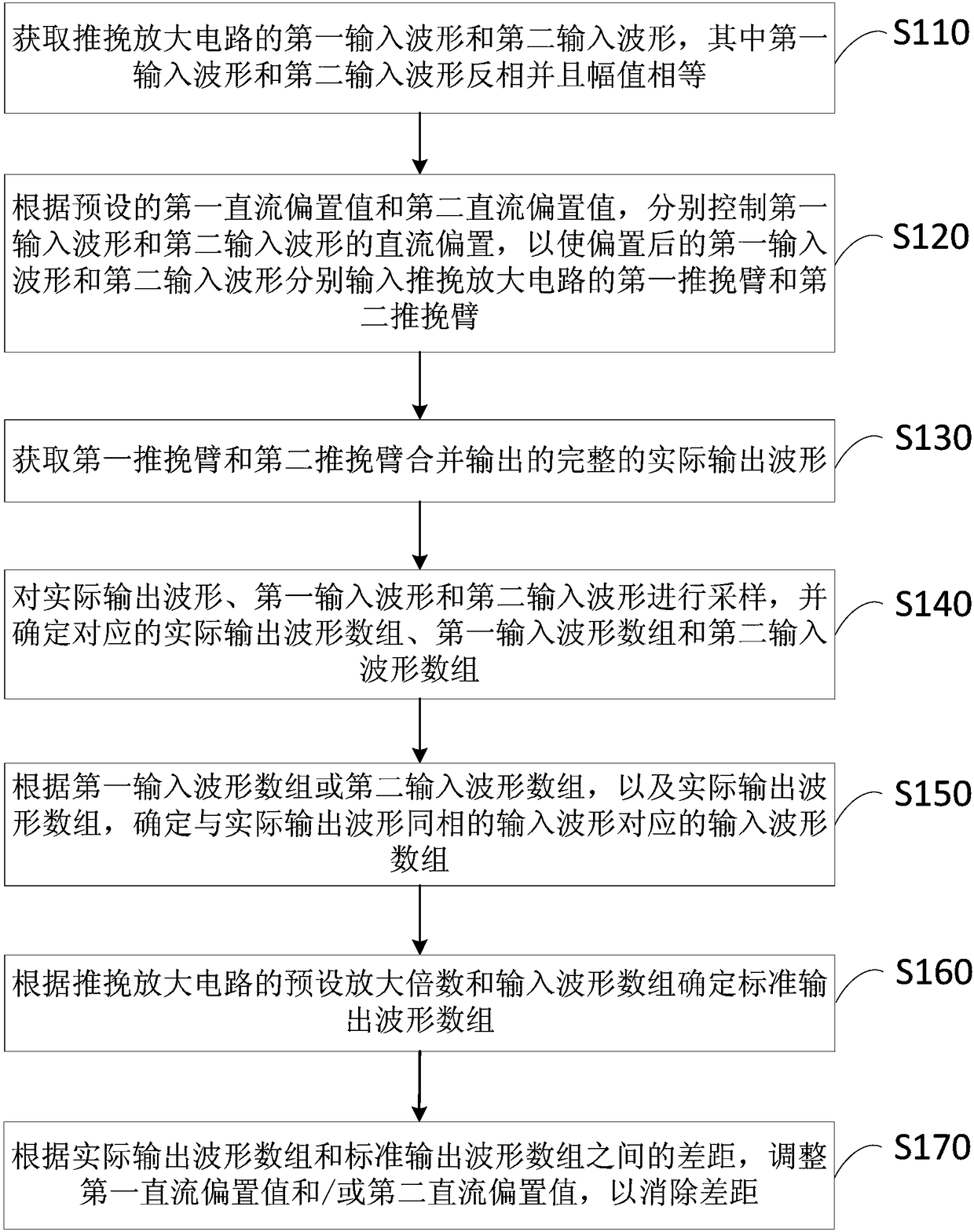
[0039] figure 1 A flow chart of a method for eliminating crossover distortion provided by Embodiment 1 of the present invention. This embodiment is applicable to the situation of eliminating crossover distortion of the output waveform of a push-pull amplifier circuit. The method can be executed by a crossover distortion elimination device , the device can be realized by means of software and / or hardware, and integrated in a signal processing computer. The method specifically includes the following steps:

[0040] S110. Acquire a first input waveform and a second input waveform of the push-pull amplifier circuit, where the first input waveform and the second input waveform are inverted and have equal amplitudes.

[0041] Among them, the push-pull amplifier circuit refers to the use of two sets of transistors with the same number and the same characteristics, which exist in the circuit in a push-pull manner, respectively responsible for the amplification of positive and negativ...

Embodiment 2

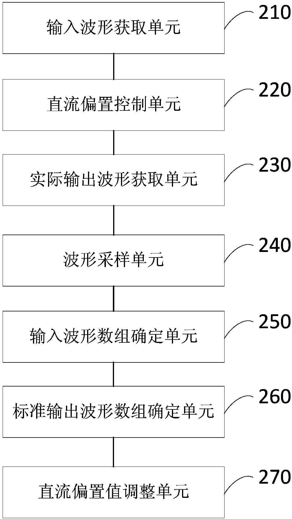
[0077] figure 2 A schematic structural diagram of a crossover distortion elimination device provided in Embodiment 2 of the present invention. This embodiment is applicable to the situation where the crossover distortion of the output waveform of a push-pull amplifier circuit is eliminated. The device specifically includes: an input waveform acquisition unit 210, DC bias control unit 220 , actual output waveform acquisition unit 230 , waveform sampling unit 240 , input waveform array determination unit 250 , standard output waveform array determination unit 260 and DC bias value adjustment unit 270 .

[0078] Wherein, the input waveform obtaining unit 210 is used to obtain the first input waveform and the second input waveform of the push-pull amplifier circuit, wherein the first input waveform and the second input waveform are inverted and equal in amplitude; the DC bias control unit 220, It is used to control the DC bias of the first input waveform and the second input wave...

Embodiment 3

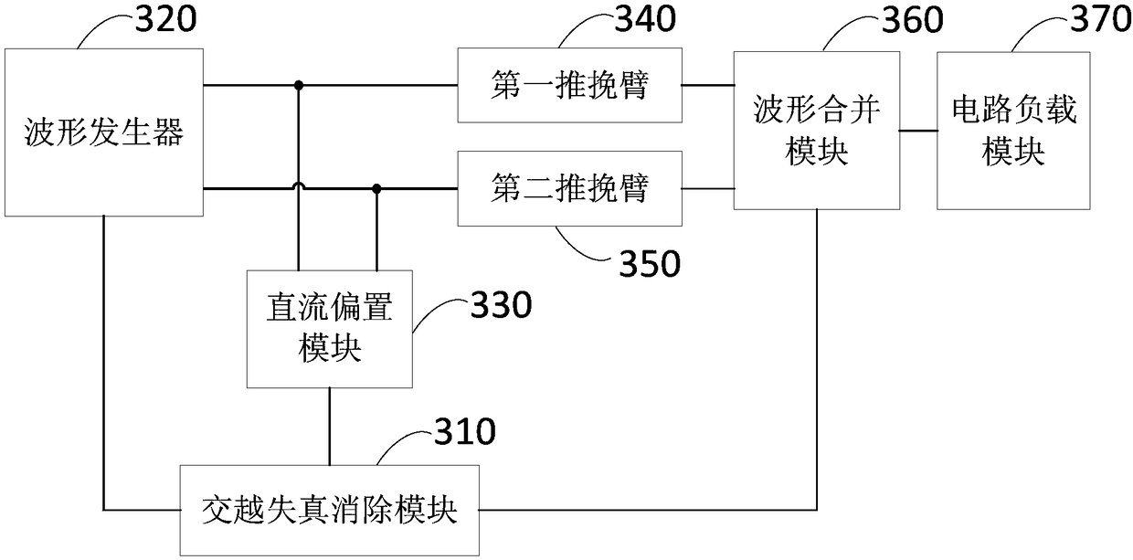
[0095] image 3 It is a schematic structural diagram of a push-pull amplifier circuit provided by Embodiment 3 of the present invention. Such as image 3 As shown, the circuit includes: a crossover distortion elimination module 310 , a waveform generator 320 , a DC bias module 330 , a first push-pull arm 340 , a second push-pull arm 350 , a waveform combining module 360 ​​and a circuit load module 370 .

[0096] Wherein, the crossover distortion elimination module 310 is connected with the waveform generator 320, the DC bias module 330 and the waveform combination module 360, and is used to realize the crossover distortion elimination method as described in any embodiment of the present invention; the waveform generator 320, Connected with the first push-pull arm 340 and the second push-pull arm 350, used to generate the first input waveform and the second input waveform, and transmit to the corresponding first push-pull arm 340 and the second push-pull arm 350; DC bias The ...


PUM


Abstract

The embodiment of the invention discloses a crossover distortion elimination method, a crossover distortion elimination device, a circuit, a computer and a storage medium. The method comprises the steps of acquiring a first input waveform and a second input waveform of a push-pull amplifier circuit; separately controlling direct current bias of the first input waveform and the second input waveform according to a preset first direct current bias value and a preset second direct current bias value; acquiring an actual output waveform of the push-pull amplification circuit; sampling the actual output waveform, the first input waveform and the second input waveform to determine a corresponding actual output waveform array, a corresponding first input waveform array and a corresponding secondinput waveform array, and determine the input waveform array which is inphase with the actual output waveform; determining a standard output waveform array according to a preset amplification factor and the input waveform array; and adjusting the first direct current bias value and / or the second direct current bias value according to the difference between the actual output waveform array and thestandard output waveform array to eliminate the difference. Therefore, the amplification performance of the push-pull amplification circuit is improved.

Description

technical field [0001] Embodiments of the present invention relate to signal processing technologies, and in particular to a crossover distortion elimination method, device, circuit, computer and storage medium. Background technique [0002] In the power amplification control system, especially in the ultrasonic control system, the shape of the output waveform of the amplification circuit has a great influence on the performance of the ultrasonic transducer. Usually, the push-pull amplifier circuit used in the power amplifier control system has a certain crossover distortion in the output waveform of the amplifier circuit due to the existence of junction voltage or conduction voltage in the triode or field effect tube, which causes the ultrasonic transducer to work in The state of distortion affects the control of the control system on the ultrasonic transducer, and even breaks and damages the piezoelectric ceramic transducer. [0003] In order to avoid crossover distortion...

Claims


Application Information

Patent Timeline
IPC IPC(8): H03F1/32H03F3/26
CPCH03F1/32H03F3/26
Inventor 不公告发明人
Owner SURGSCI SHENZHEN MEDICAL TECH CO LTD
Learn More