
Reinforced composite metal structure and moulding method and application thereof

A composite metal and metal structure technology, which is applied in the field of metal composite materials, can solve the problems of increasing the difficulty of processing, the difference in cooling speed, and the difficulty of endogenous strengthening phases to bear stress uniformly.

Pending Publication Date: 2018-07-13
DONGGUAN JIANYE MATERIAL TECH CO LTD
View PDF9 Cites 0 Cited by
  • Summary
  • Abstract
  • Description
  • Claims
  • Application Information

AI Technical Summary

Problems solved by technology

[0004] Although the above technical solutions have been disclosed in many documents and patents, and many researchers have made more detailed improvements to them, such as adding connection structures, they have not been widely used in actual manufacturing technology. The reason is that the distribution uniformity of the endogenous strengthening phase in the above technology is difficult to control due to the difference in the cooling rate of each part of the product. It is difficult for the phase to bear the stress uniformly, resulting in inconsistent strain levels and easy to cause fracture.
In view of the above insurmountable shortcomings, some relevant surface stress treatment and surface coating technical solutions have also been proposed, both of which form a deformation-resistant structure on the surface of the amorphous alloy, in order to offset the hot compressive stress and reduce the pressure on the internal surface. However, in the actual fracture mode of the product, the technical effects of surface stress treatment and surface coating are very limited, and surface stress treatment and surface coating structure are new processes, which have greatly improved after the increase. The difficulty of the overall process, which directly increases the cost of the prepared product, further limits the application of this technology

Method used


Image

  • Reinforced composite metal structure and moulding method and application thereof
  • Reinforced composite metal structure and moulding method and application thereof
  • Reinforced composite metal structure and moulding method and application thereof

Examples


Embodiment 1

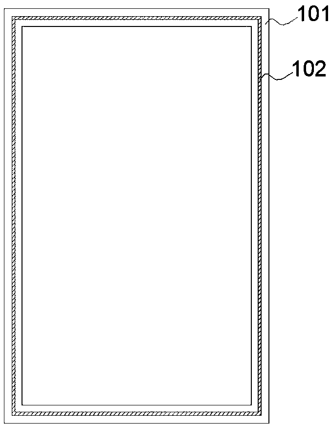
[0034] as attached figure 1 Shown is an application of the reinforced composite metal structure in the present invention. The structure is used as an outer frame of a product, and can be applied to outer frame structures such as smart phones, tablet computers, and communication products.

[0035] The structure includes a main metal frame structure 101 (a zirconium-based amorphous alloy product) and a reinforcement structure 102 . In this embodiment, the reinforcement structure 102 is a similar frame structure embedded in the outer frame 101 . . In the actual manufacturing process, when the reinforcing structural member 102 is an integral piece, it is easy to cause unevenness in the injection and pressurization of the raw materials during the processing process. Therefore, in this embodiment, the reinforcing structural member 102 is preferably set as a two-symmetrical half-frame structure The shape structure of the reinforcing structural member 102 is formed by splicing, or se...

Embodiment 2

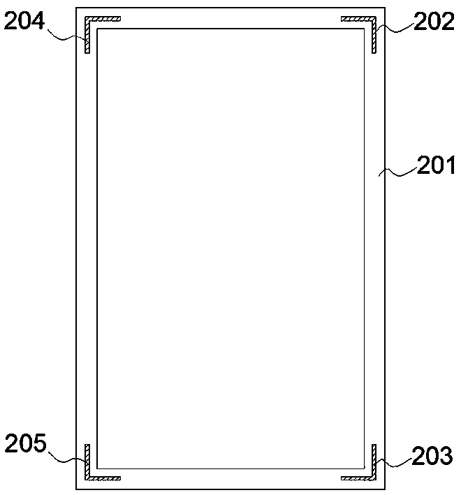
[0038] as attached figure 2Shown is another application of the reinforced composite metal structure in the present invention. The difference from Embodiment 1 is that the structure includes a main metal frame structure 201 (a zirconium-based amorphous alloy part) and a reinforced component. The strong components are angled structural members 202 , 203 , 204 , and 205 distributed at four corners of the frame structure 201 . In the frame structure, the four corners of the main metal structure are the areas that are most easily deformed by external forces. For example, the corners of smartphones are the most severely damaged and deformed in the drop test. Therefore, independent reinforcement structures are installed at the corners. It has a very good protective effect on the frame structure.

Embodiment 3

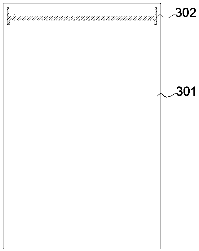
[0040] as attached image 3 Shown is another application of the reinforced composite metal structure in the present invention. The structure includes a main metal frame structure 301 (a magnesium-based amorphous alloy part) and a reinforced structural member 302, which is inlaid and composited. The frame structure 301 is reinforced in the form of outsourcing. It can be seen from the accompanying drawings that the vertical structures of the reinforcing structural members 302 disposed on both sides penetrate the frame structure 301, and the horizontal bar structure in the middle connects the vertical structures on both sides to form the reinforcing structural member as a whole, that is, the reinforcing structural member 302 is partially connected to the metal frame structure 301 .

[0041] In this embodiment, a transitional connection method can also be used, and the transitional connection method is specifically provided with a transitional connection piece as an intermediate ...


PUM


Abstract

The invention discloses a reinforced composite metal structure. The reinforced composite metal structure comprises a main body metal structure and a reinforcing component; the reinforcing component isconnected with the main body metal material in an embedded, externally-wrapping, penetrating, partially-connection or transition-connection mode; the reinforcing component comprises one or more reinforcing structural elements; a part, which is embedded the main body metal structure, of each single reinforcing structural element accounts for 5-100% of the reinforcing structural element; and each reinforcing structural component has a matched preset shape according to features of the main body metal structure, and is arranged at a partial zone, which needs to be reinforced, in the main body metal structure. According to the reinforced composite metal structure, a mode of embedding the prefabricated reinforcing components is adopted, so that the prefabricated reinforcing components are deeply combined with an amorphous alloy base body; when a products adopting the mode is encountered with a force generated by bending or impacting, a mutual supporting structure is formed by the prefabricated reinforcing components and the amorphous alloy base body; and in an elastic range of the amorphous alloy base body, double protection is formed for electronic elements or other parts in the product.

Description

technical field [0001] The invention belongs to the field of metal composite materials, and in particular relates to a composite metal structure with reinforcing function and a forming method and application thereof. Background technique [0002] Metal material is one of the most commonly used materials in national production and life. It has the advantages of high strength, high hardness, and good appearance and texture. It has a very wide range of applications in the fields of construction, military industry, aerospace, 3C electronics, and daily necessities. Amorphous alloy material is a new type of metal material that has developed rapidly in recent years. It has high specific strength, specific modulus, high hardness, wear resistance and corrosion resistance. It has been used in aerospace, automotive sports products, consumer electronics. It has been applied in other fields and attracted more and more attention. However, due to the unique microstructure characteristics ...

Claims


Application Information

Patent Timeline
Patent Type & Authority Applications(China)
IPC IPC(8): B22D19/02B22D27/09
CPCB22D19/02B22D27/09
Inventor 黄利敏
Owner DONGGUAN JIANYE MATERIAL TECH CO LTD
Learn More