Grinding device with waste scrap recovery function

A grinding device and functional technology, which is applied in the field of grinding devices with waste recycling function, can solve the problems of inconvenient feeding, low feeding efficiency, and low working efficiency, and achieve convenient feeding, sufficient grinding, and improved working efficiency Effect

Inactive Publication Date: 2018-07-13
湖州铭之远研磨科技有限公司
View PDF0 Cites 5 Cited by
  • Summary
  • Abstract
  • Description
  • Claims
  • Application Information

AI Technical Summary

Problems solved by technology

[0002] The main part of the grinding device is the grinding machine. The grinding machine is a grinding machine for grinding metal workpieces with grinding tools and abrasive materials. The existing grinding machines generally use a vibration motor to drive the workpiece and the abrasive to rub against each other. The grinding machine has The fixed-size cavity is used to load the workpiece and abrasive to be processed. It is impossible to change the size of the grinding cavity according to the number of processed workpieces. The application range is narrow. The vibration motor drive method makes it easy for the workpiece to gather at the bottom of the grinding cavity during the grinding process. , so that the workpiece is not sufficiently ground, and manual stirring is often required to adjust the distribution between the processed workpiece and the abrasive, and the work efficiency is low; It is convenient, and then the processed workpiece, abrasive and waste are separated by the principle of a filter screen. The waste will adhere to the surface of the workpiece and abrasive, which is difficult to clean. There is no recovery device that can complete the processed workpiece and abrasive during the blanking process. Separation and recycling of waste
Therefore, the existing grinding device has the disadvantages of being unable to adjust the size of the grinding chamber according to the amount of processed workpieces, poor workpiece grinding effect, low blanking efficiency, and difficult to recycle the waste generated by grinding.

Method used


Image

  • Grinding device with waste scrap recovery function
  • Grinding device with waste scrap recovery function
  • Grinding device with waste scrap recovery function

Examples


Embodiment

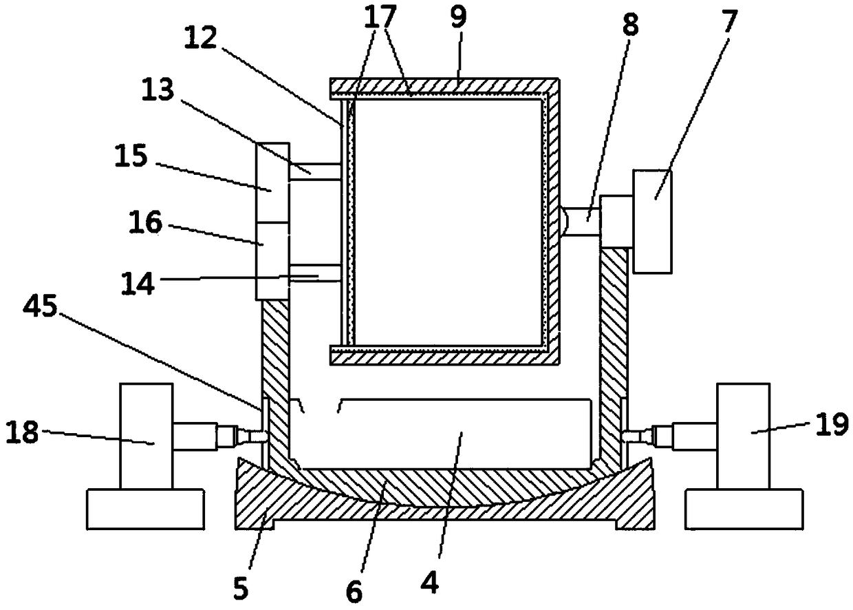
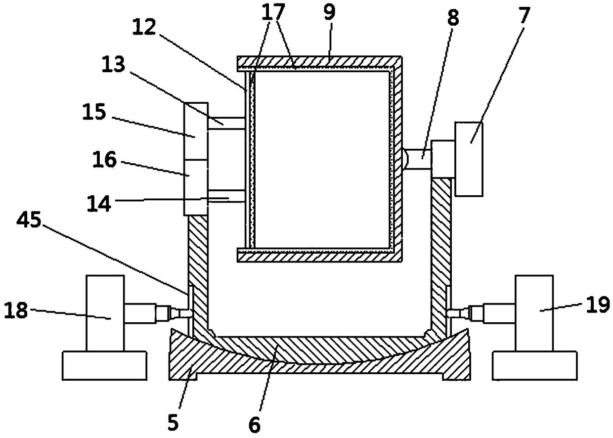
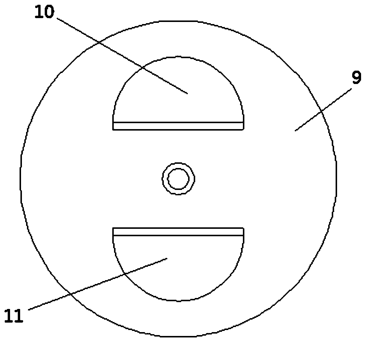
[0021] Embodiment: the grinding device with waste chip recovery function, structure such as Figures 1 to 5 As shown, a grinder 1 is included, and a blanking device 4 is arranged in the grinder 1; the grinder 1 includes a lower base 5, an upper base 6 is arranged above the lower base 5, and the upper base 6 is connected with a first rotating motor 7, The first rotating motor 7 is connected with a grinding chamber 9 without a cover through the rotating shaft 8. The grinding chamber 9 is respectively provided with a workpiece inlet 10 and a flow abrasive inlet 11. One side of the grinding chamber 9 is provided with a grinding cover 12, and the grinding cover The body 12 is symmetrically provided with a first telescopic rod 13 and a second telescopic rod 14, the first telescopic rod 13 is connected with a first push rod motor 15, the second telescopic rod 14 is connected with a second push rod motor 16, and the grinding cavity 9 The inner surface of the inner surface and the grin...


PUM


Abstract

The invention discloses a grinding device with a waste scrap recovery function. The grinding device comprises a grinding machine, and a discharging device is arranged in the grinding machine. The grinding machine comprises a lower base. An upper base is arranged above the lower base and is connected with a first rotary motor. The first rotary motor is connected with a cover-free grinding cavity through a rotary shaft. The grinding cavity is provided with a workpiece inlet and a flowing grinding material inlet. A grinding cover is arranged on one side of the grinding cavity and is symmetricallyprovided with a first telescopic rod and a second telescopic rod. The first telescopic rod is connected with a first push rod motor, and the second telescopic rod is connected with a second push rodmotor. Fixed grinding materials are embedded on the inner surface of the grinding cavity and the grinding cover. A first electric-hydraulic push rod and a second electric-hydraulic push rod are arranged on the two sides of the upper base correspondingly. The grinding device has the advantages that the size of the grinding cavity can be adjusted according to the machined workpiece quantity, the workpiece grinding effect is good, the discharging efficiency is high, and waste scraps generated by grinding can be recycled.

Description

technical field [0001] The invention relates to a grinding device, in particular to a grinding device with waste recycling function. Background technique [0002] The main part of the grinding device is the grinding machine. The grinding machine is a grinding machine for grinding metal workpieces with grinding tools and abrasive materials. The existing grinding machines generally use a vibration motor to drive the workpiece and the abrasive to rub against each other. The grinding machine has The fixed-size cavity is used to load the workpiece and abrasive to be processed. It is impossible to change the size of the grinding cavity according to the number of processed workpieces. The application range is narrow. The vibration motor drive method makes it easy for the workpiece to gather at the bottom of the grinding cavity during the grinding process. , so that the workpiece is not sufficiently ground, and manual stirring is often required to adjust the distribution between the...

Claims


Application Information

Patent Timeline
Patent Type & Authority Applications(China)
IPC IPC(8): B24B31/02B24B31/12B24B31/16B24B55/12
CPCB24B31/02B24B31/12B24B31/16B24B55/12Y02P70/10
Inventor 赵剑波
Owner 湖州铭之远研磨科技有限公司
Why Eureka
Try Eureka