Cofferdam structure for water taking head structure construction in river and construction method thereof

A construction method and technology of water intake head, applied in the direction of basic structure engineering, construction, etc., can solve the problems of large adverse impact on the front end of the cofferdam, insignificant pumping effect, impact, etc., and achieve the effect of ensuring the quality of structural construction

Active Publication Date: 2018-07-13
CHINA MCC5 GROUP CORP
View PDF6 Cites 2 Cited by
  • Summary
  • Abstract
  • Description
  • Claims
  • Application Information

AI Technical Summary

Problems solved by technology

[0002]In the construction project of the applicant's water intake head structure, according to the design requirements, the water intake head structure needs to be constructed at a distance of 400m from the pump house to form a circle The cofferdam, the top of the cofferdam at the water intake head is 6m away from the river bed, and the height difference between the river bed and the bottom of the water intake head structure is 6m, and there is a height difference of about 9 meters behind the cofferdam. With the progress of the cofferdam extension, the river channel gradually narrows, which is bound to As a result, the water flow is turbulent and the water depth increases, which has a great adverse effect on the structural part of the front end of the cofferdam, and a large amount of leakage of the cofferdam has occurred. The simultaneous operation of 10 water pumps cannot effectively reduce the water level caused by leakage in the cofferdam, and the pumping effect It is not obvious, and the location of the exact leakage point of the cofferdam seepage cannot be determined, and the construction period is very tight. At the same time, when excavating the foundation pit of the water intake structure, piping and quicksand will occur in the cofferdam, which seriously affects the construction safety. The accumulation of water in the construction area of ​​the foundation pit cannot effectively construct the area of ​​the water intake head structure. In addition, the turbulent water flow and the piping and quicksand in the cofferdam structure will affect the stability of the entire cofferdam weir structure. The structural stability of the cofferdam is the basic condition to ensure the safety and reliability of the construction work in the cofferdam

Method used


Image

  • Cofferdam structure for water taking head structure construction in river and construction method thereof
  • Cofferdam structure for water taking head structure construction in river and construction method thereof
  • Cofferdam structure for water taking head structure construction in river and construction method thereof

Examples


Embodiment 1

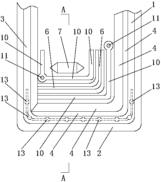
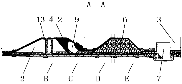
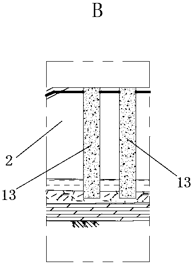
[0027] Such as Figures 1 to 6 As shown, the cofferdam structure used for the construction of the water intake head structure in the river includes the peripheral weir. The peripheral weir includes the upper cofferdam 1, the end cofferdam 2 and the lower cofferdam 3 connected in sequence. The inner side of the end cofferdam 2 Widening cofferdam 4 is provided on the inner side of the front end of upper cofferdam and upper cofferdam 1, composite geomembrane 5 is laid between widening cofferdam 4 and end cofferdam 2 and upper cofferdam 1, widening cofferdam 4 and lower cofferdam 3 is built with an inner cofferdam 6, and the construction area of ​​the water intake head structure 7 is located in the area between the lower cofferdam 3 and the inner cofferdam 6, and the inner cofferdam 6 blocks the front end and the upstream end of the water intake head structure 7, One end of the inner cofferdam 6 is connected with the construction of the lower cofferdam 3, and the slope ratio range...

Embodiment 2

[0030] Such as figure 1 , 2 , 5 to 7, on the basis of Embodiment 1, an open drainage ditch 10 is arranged between the inner cofferdam 6 and the widening cofferdam 4, and the track of the open drainage ditch 10 is parallel to the track of the widening cofferdam 4, and the open drainage ditch The trajectory of 10 blocks the construction trajectory of the inner cofferdam 6. One end of the open drainage ditch 10 is connected to a sump 11. The longitudinal gradient of water diversion of the open drainage ditch 10 is 1% to 3%. The sump 11 is lower than the open drainage ditch 10. The lowest point of the inner cofferdam 6 and the water intake head structure 7 is also provided with an open drainage ditch 10, the track of the open drainage ditch 10 is parallel to the track of the inner cofferdam 6, and the track of the open drainage ditch 10 blocks the front end of the water intake head structure 7, At the upstream end and the downstream end, the open drainage ditch 10 is also connect...


PUM


Abstract

The invention relates to the technical field of cofferdams, and discloses a construction method of a cofferdam structure for the water taking head structure construction in a river. A first widened cofferdam is arranged on the inner side of the end cofferdam of an outer cofferdam. A second widened cofferdam is arranged on the inner side of the front end of an upper cofferdam. Composite geomembraneis laid between the first widened cofferdam and the end cofferdam and between the second widened cofferdam and the upper cofferdam. An inner cofferdam is built between the first widened cofferdam andthe lower cofferdam. The construction area of the water taking structure is located on the area between the lower cofferdam and the inner cofferdam. A plurality of pile bodies are arranged at the front end of the upper cofferdam and the front end of the lower cofferdam, and in the cofferdam body of the end cofferdam in a high-pressure jet grouting manner. A waterproof curtain is formed between every two adjacent pile bodies. According to the construction method of the cofferdam structure for the water taking head structure construction in the river, because of the widened cofferdams, the composite geomembrane and the pile bodies, the seepage amount of the part, at the front end, of the structure of of the outer cofferdam is greatly reduced, and the structural strength of the outer cofferdam is enhanced; and meanwhile, because of the inner cofferdam, the construction operation in the construction area of the water taking head structure is safer and more reliable, and construction operation can be effectively carried out on the water taking head structure.

Description

technical field [0001] The invention relates to the technical field of cofferdams, in particular to a construction method of a cofferdam structure used for construction of a water intake head structure in a river. Background technique [0002] In the construction project of the applicant's water intake head structure, according to the design requirements, the water intake head structure needs to be constructed with a cofferdam 400m away from the pump house to form a circle of peripheral weirs. The top of the water intake head is 6m away from the river bed, and the river bed The height difference from the bottom of the water intake head structure is 6m, and there is a height difference of about 9 meters behind the cofferdam. With the progress of the cofferdam extension, the river channel gradually narrows, which will inevitably lead to turbulent water flow and increased water depth, which is not good for the structural part of the front of the cofferdam. The impact is relativ...

Claims


Application Information

Patent Timeline
Patent Type & Authority Applications(China)
IPC IPC(8): E02D19/04
CPCE02D19/04Y02E10/20
Inventor 徐茂钦邬静芝王祥
Owner CHINA MCC5 GROUP CORP
Why Eureka
Try Eureka