Full-automatic busbar lifting frame hydraulic system capable of effectively reducing return oil back pressure
A hydraulic system, fully automatic technology, applied in the direction of fluid pressure actuators, servo motor components, mechanical equipment, etc., can solve the problems of energy saving and emission reduction, insufficient integration and intelligence of the system, wear and tear of components, etc., to achieve Effects of reducing recoil damage failure, improving smart operability, and compact arrangement of components
- Summary
- Abstract
- Description
- Claims
- Application Information
AI Technical Summary
Problems solved by technology
Method used
Image

Examples
Embodiment Construction
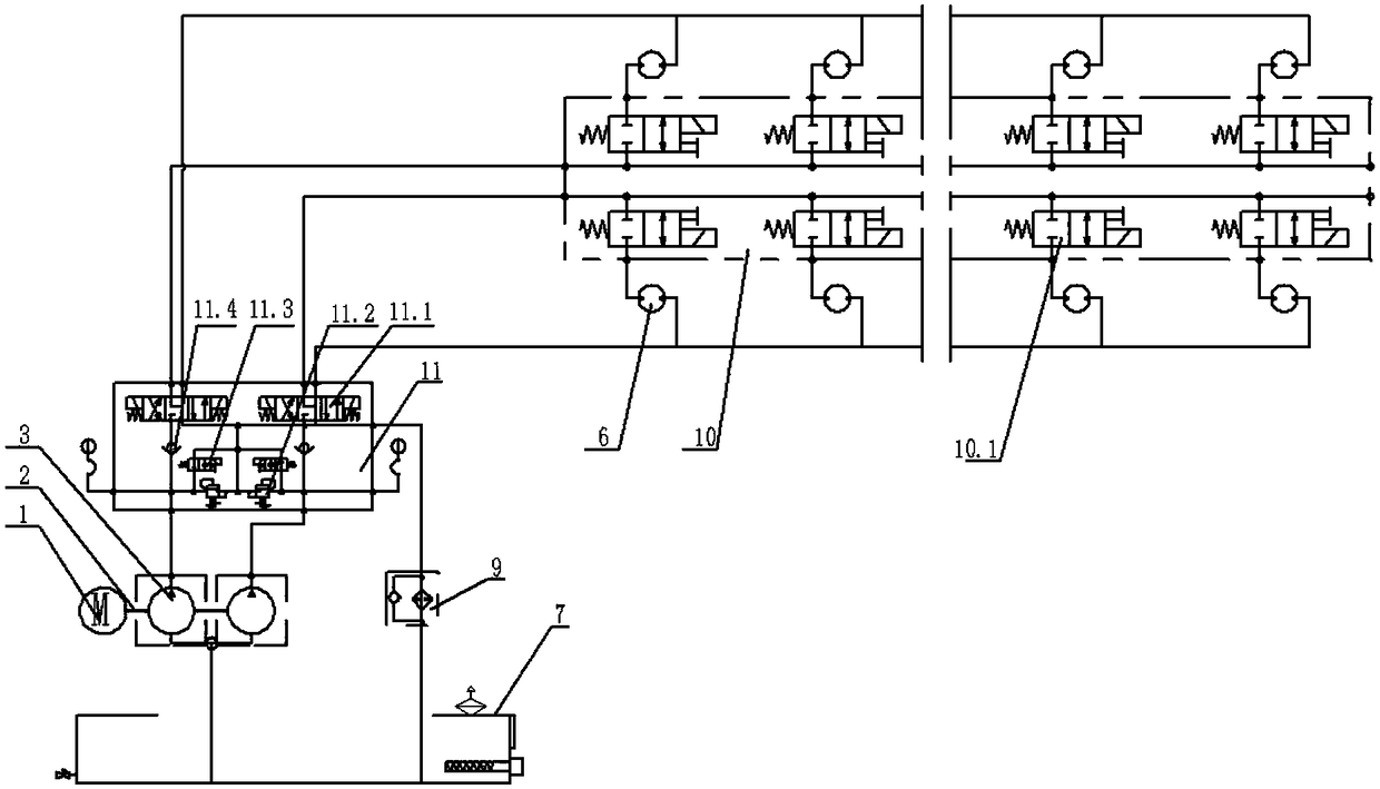
[0024] as attached figure 1 As shown in , the fully automatic anode bus lifting frame optimization system consists of a set of motors 1, couplings / bell housings 2, a set of double series hydraulic pumps 3, hydraulic systems and electrical systems.
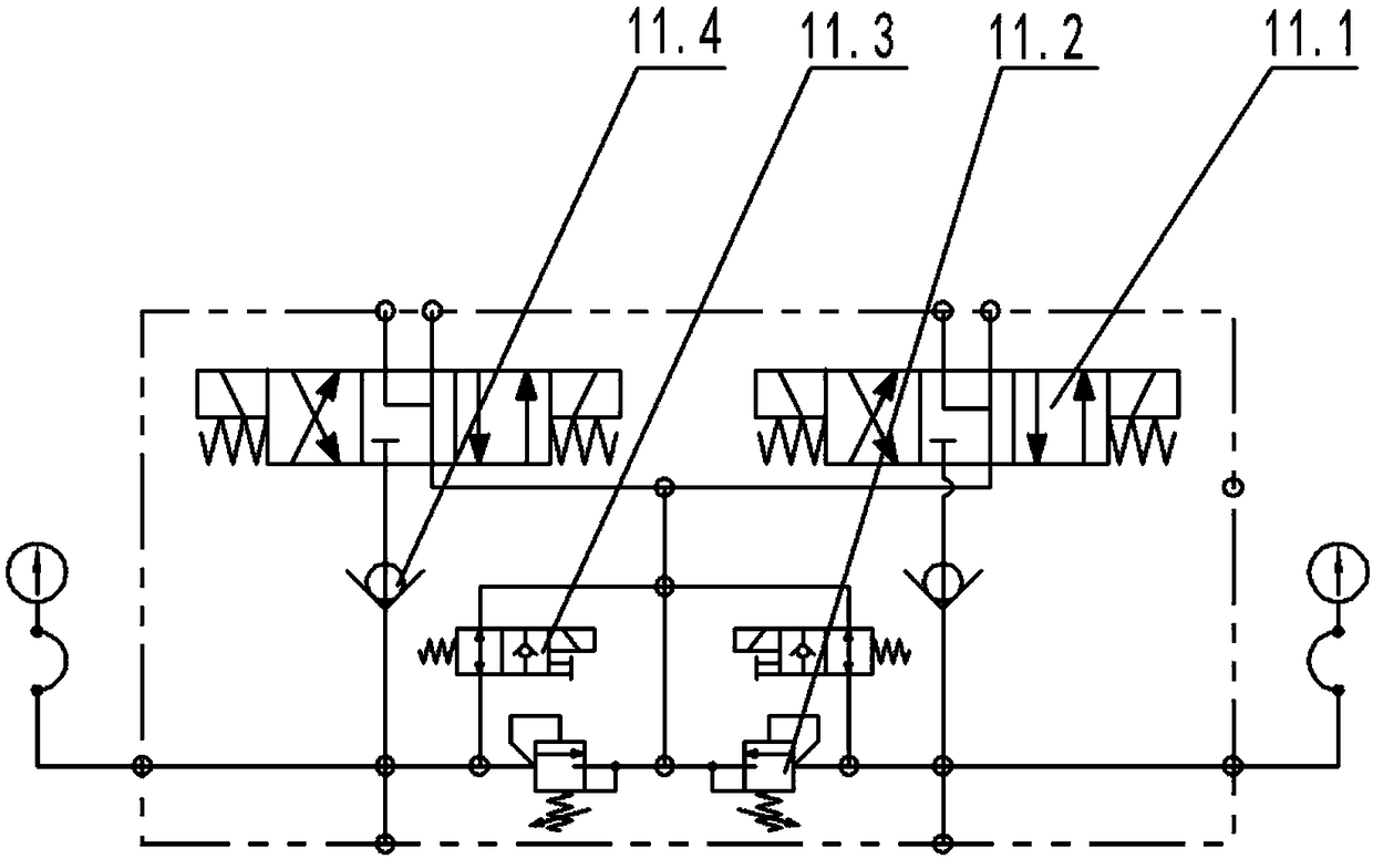
[0025] The hydraulic system includes a hydraulic pump 3, a hydraulic motor 6, a hydraulic oil tank 7, an oil return filter 9, an integrated valve group 10, a pump control valve group 11, and auxiliary parts such as pipelines and joints connecting hydraulic components. One of the motors 1 drives a set of double-connected hydraulic pumps 3 through a set of couplings / bell housings 2, and the oil suction pipes jointly suck oil from the hydraulic oil tank 7, and the high-pressure oil first passes through the more integrated pump control valve group 11 before Through the output of two electromagnetic reversing valves 11.1, the rotation and stop of the hydraulic motor 6 can be realized by controlling the on-off of the plug-in two-way elec...
PUM
 Abstract
Description
Claims
Application Information
 - R&D
- Intellectual Property
- Life Sciences
- Materials
- Tech Scout
- Unparalleled Data Quality
- Higher Quality Content
- 60% Fewer Hallucinations
Browse by: Latest US Patents, China's latest patents, Technical Efficacy Thesaurus, Application Domain, Technology Topic, Popular Technical Reports.
© 2025 PatSnap. All rights reserved.Legal|Privacy policy|Modern Slavery Act Transparency Statement|Sitemap|About US| Contact US: help@patsnap.com