
Molybdenum disulfide flexible ion sensor

An ion sensor, molybdenum disulfide technology, applied in the field of MEMS, can solve the problems of affecting long-term stability, increasing noise, submerging effective signals, etc., to achieve the effect of improving long-term stability, improving long-term stability, and avoiding environmental impact

Pending Publication Date: 2018-07-13
TSINGHUA UNIV
View PDF7 Cites 3 Cited by
  • Summary
  • Abstract
  • Description
  • Claims
  • Application Information

AI Technical Summary

Problems solved by technology

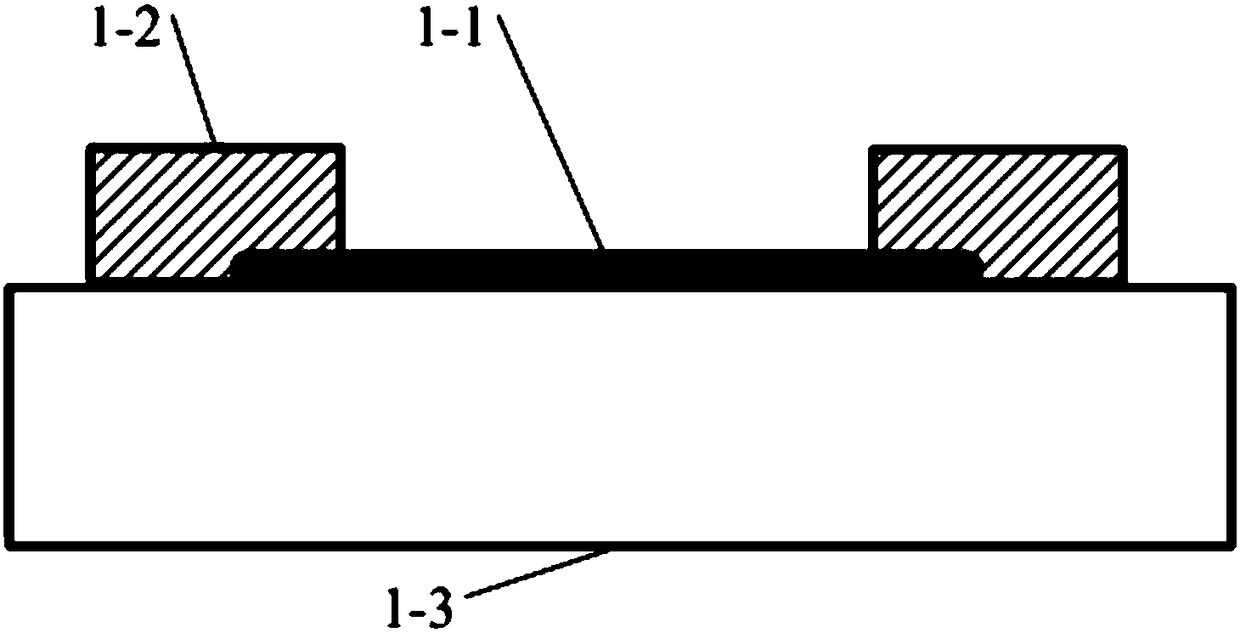
[0003] The performance of the molybdenum disulfide sensor reported in the literature is restricted by the structure of the device. The common structure of the molybdenum disulfide ion sensor in the prior art is detailed in figure 1 , in the figure, 1-1—molybdenum disulfide, 1-2—metal electrode, 1-3—substrate; molybdenum disulfide 1-1 is in direct contact with substrate 1-3, and the dangling bonds on the surface of the substrate carry current to the interior of molybdenum disulfide The particles form strong scattering, increase the noise, and submerge the effective signal, so that the device cannot reach the ultra-low detection limit it should have
The upper surface of molybdenum disulfide is exposed to the air for a long time, and oxygen, water vapor, etc. will gradually degrade its electrical properties, causing significant drift in device performance and affecting long-term stability (Selective gas sensing with h-BN capped MoS 2 heterostructural thin-film transistors, G. Liu, IEEE Electron Device Letters, 2015, 36, 1202-1204
The above non-ideal factors make MoS 2 Excellent material properties cannot be fully utilized, reducing sensor performance

Method used


Image

  • Molybdenum disulfide flexible ion sensor
  • Molybdenum disulfide flexible ion sensor
  • Molybdenum disulfide flexible ion sensor

Examples


Embodiment Construction

[0024] The technical scheme of the present invention will be further described below in conjunction with the drawings and embodiments.

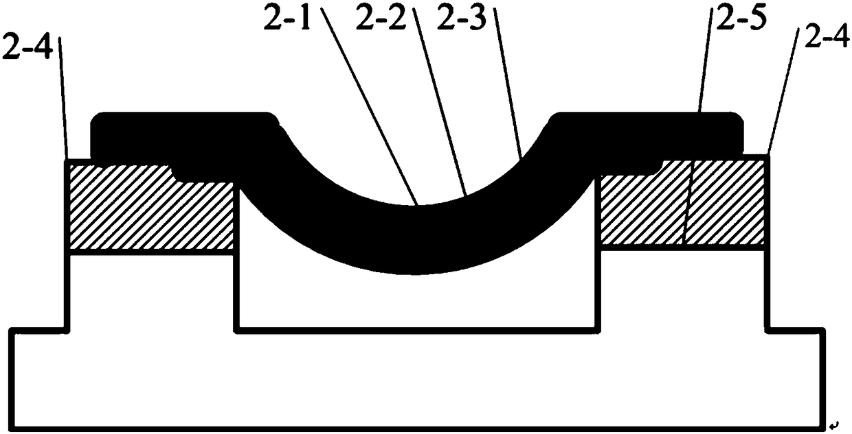
[0025] Reference image 3 , Figure 4 , A molybdenum disulfide flexible ion sensor, characterized in that it comprises a boron nitride layer 2-1, a molybdenum disulfide layer 2-2, a boron nitride layer 2-3, and a metal electrode 2 connected together from top to bottom. -4 and the flexible substrate 2-5; the molybdenum disulfide layer 2-2 is located below the boron nitride layer 2-1 and above the boron nitride layer 2-3, and the molybdenum disulfide layer 2-2 and the boron nitride The layer 2-1 and the boron nitride layer 2-3 constitute a composite beam structure, the two ends of the composite beam are respectively connected with the metal electrodes 2-4, and the middle part of the composite beam is suspended; the flexible substrate 2-5 is located in the suspension of the composite beam structure Part below.

[0026] The molybdenum disulfide layer...


PUM


Abstract

A molybdenum disulfide flexible ion sensor comprises a boron nitride layer (2-1), a molybdenum disulfide layer and a boron nitride layer (2-3) which are connected together from top to bottom, a metalelectrode and a flexible substrate, wherein the molybdenum disulfide layer is located under the boron nitride layer (2-1) and located above the boron nitride layer (2-3); a composite beam structure isformed by the molybdenum disulfide layer, the boron nitride layer (2-1) and the boron nitride layer (2-3); two ends of a beam are respectively in contact with the metal electrode, and the middle partof the beam is suspended in midair; the flexible substrate is located under the suspended part of the composite beam structure. The boron nitride layer (2-1) is used as a protective layer, so that the upper surface and the lower surface of the molybdenum disulfide layer can be prevented from being in contact with air and water vapor in the air, and the molybdenum disulfide layer can be preventedfrom degenerating in the air; a suspended structure is capable of preventing the molybdenum disulfide layer from being in direct contact with the flexible substrate, so that scattering influence of the flexible substrate to the molybdenum disulfide layer can be avoided; the structure is capable of enabling a molybdenum disulfide ion sensor to obtain better lower detection limit, increasing long-term stability and reducing the influence of deformation of the flexible substrate to a device.

Description

Technical field [0001] The present invention relates to the technical field of MEMS, in particular to a molybdenum disulfide flexible ion sensor, which is a suspended molybdenum disulfide sensor structure with a boron nitride protective layer, which can enable the molybdenum disulfide ion sensor to obtain a better lower detection limit , Improve long-term stability and reduce the influence of deformation on the device. Background technique [0002] At present, the bottleneck in the development of wearable flexible sensors is that the performance of sensitive materials cannot meet the demand. The appearance of two-dimensional material molybdenum disulfide brings hope to solve the above problems. Molybdenum disulfide has a large specific surface area (which can improve sensitivity; extremely low noise (which can obtain a better detection limit; high fracture strain (bending resistance; easy processing and integration potential), so it is an ideal sensitive material. [0003] The pe...

Claims


Application Information

Patent Timeline
IPC IPC(8): G01N27/12
CPCG01N27/128
Inventor 李鹏
Owner TSINGHUA UNIV
Learn More