Chip clamping device of resistance chip grinding machine

A technology of resistance sheet and grinding sheet, which is applied in the direction of grinding drive device, grinding/polishing safety device, resistor, etc. problem, to achieve the effect of high practical value, consistent pattern and reduced gap

Pending Publication Date: 2018-07-17
NANYANG ZHONGXIANG POWER ELECTRONICS
View PDF0 Cites 0 Cited by
  • Summary
  • Abstract
  • Description
  • Claims
  • Application Information

AI Technical Summary

Problems solved by technology

Miniaturized tank arresters require small resistors, and the small resistors are polished flat. At present, it is known that the production process of small resistors is completed by people, clamps, and grinding machines. During the production process, when the staff used clamps to clamp the resistance piece and sent it into the grinding machine, the contact between the resistance piece and the grinding disc of the grinding machine was inconsistent due to the force and speed generated by friction, and the patterns on the two polishing surfaces of the resistance piece were messy. When two resistors are stacked and used, the gap between the polished surfaces of the two chips is slightly larger, which affects the appearance of the resistor, and the product qualification rate is unstable, which affects product quality. In addition, the existing manual operation of the resistor has low production efficiency. high production cost

Method used


Image

  • Chip clamping device of resistance chip grinding machine
  • Chip clamping device of resistance chip grinding machine
  • Chip clamping device of resistance chip grinding machine

Examples


Embodiment Construction

[0017] The following will be described in detail in conjunction with the technical solutions in the embodiments of the present invention:

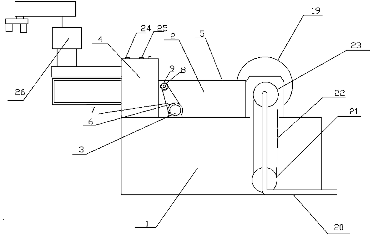
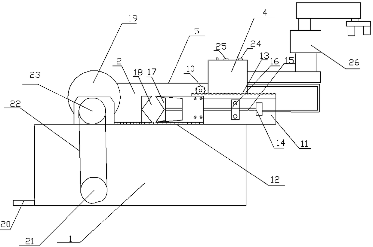
[0018] see figure 1 , figure 2 As shown, a clamping device of a resistive disc grinding machine includes a grinding machine 1 and a clamping device 2, and the clamping device 2 is fixed on the grinding machine 1 by bolts; the clamping device 2 includes a single-phase The speed-regulating motor 3, the circuit control device 4 for controlling the single-phase speed-regulating motor 3, the rear steel plate 5 and the chassis for fixing the single-phase speed-regulating motor 3 and the rear steel plate 5, and the clamping device 2 is used by the chassis. Bolts are fixed on the grinding machine 1; the output shaft of the single-phase speed-regulating motor 3 is connected to the chain wheel 6, the chain wheel 6 is connected to the chain 7, and the other end of the chain 7 is connected to the transmission shaft 8, and the transmission shaft 8 pa...


PUM


Abstract

The invention discloses a chip clamping device of a resistance chip grinding machine. The device comprises a chip grinding machine, a chip clamping device and an intelligent manipulator; the chip clamping device comprises a single-phase speed adjusting motor, a circuit control device for controlling the single-phase speed adjusting motor, and a back steel plate; an output shaft of the single-phasespeed adjusting motor is connected with a chain wheel; the chain wheel is connected with a chain; the other end of the chain is connected with a transmission shaft; the transmission shaft is connected with a gear after penetrating through the back steel plate through a steel sleeve; a chip clamping mechanism and a steel rail for fixing the chip clamping mechanism are arranged on the side, near the gear, of the back steel plate; and the chip clamping mechanism comprises a rack cooperating with the gear, an electric handle, a lead screw, a fixing block for fixing the lead screw, a slide block,and a clamping groove cooperating with the slide block for fixing resistance chips. The device enables the resistance chips and mechanical parts to achieve constant-speed advancement, retreating and speed adjustment, enables polished resistance chips to achieve consistent patterns, guarantees reduction of gaps between two laminated resistance chips, and realizes intelligent control in the whole process without staff participation.

Description

technical field [0001] The invention belongs to the technical field of lightning arresters for electric power systems, and in particular relates to a clamping device for a resistance plate grinding machine. Background technique [0002] Zinc oxide resistors are the core components of surge arresters for power grid operation protection equipment. At present, the potential gradient of existing zinc oxide resistors is low, generally ranging from 190 to 220V / mm. As the voltage of the protective equipment increases, the number of superimposed zinc oxide resistors used in the arrester will increase accordingly, and the volume and weight will increase accordingly, and the height cannot be reduced, which cannot meet the requirements of equipment miniaturization, especially with the development of power system GIS Widely used, it is imminent to require the miniaturization of the matching tank arrester. [0003] The existing resistors are divided into large resistors and small resist...

Claims


Application Information

Patent Timeline
IPC IPC(8): B24B27/00B24B41/00B24B41/06B24B55/02B24B47/20H01C17/00
CPCH01C17/00B24B27/0046B24B41/005B24B41/06B24B47/20B24B55/02H01C7/12
Inventor 韦国松刘品德刘斌康定增王春虎李秀坤
Owner NANYANG ZHONGXIANG POWER ELECTRONICS
Why Eureka
Try Eureka