

Clamp connection-type connecting device in sleeve and its connection structure and installation method thereof
A connecting device and connecting structure technology, applied in structural elements, building components, building structures, etc., can solve problems such as high connection strength, hidden dangers in building safety, and difficult quality control, so as to improve bearing capacity, improve connection strength, and install easy effect
- Summary
- Abstract
- Description
- Claims
- Application Information
AI Technical Summary
Problems solved by technology
Method used
Image

Examples
Embodiment 1
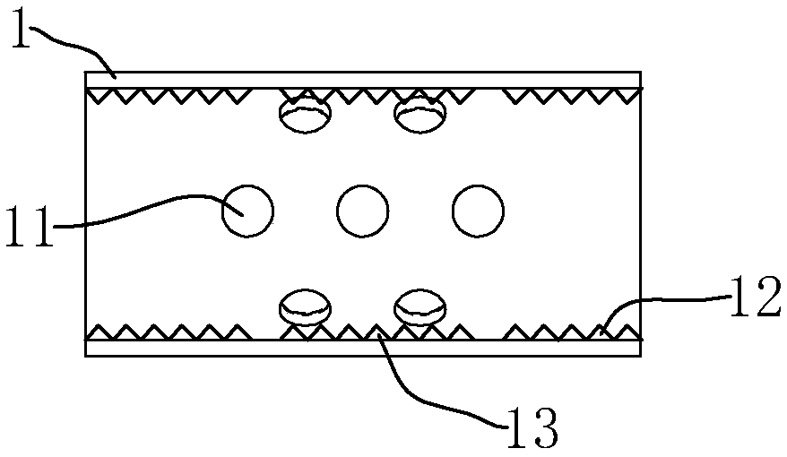
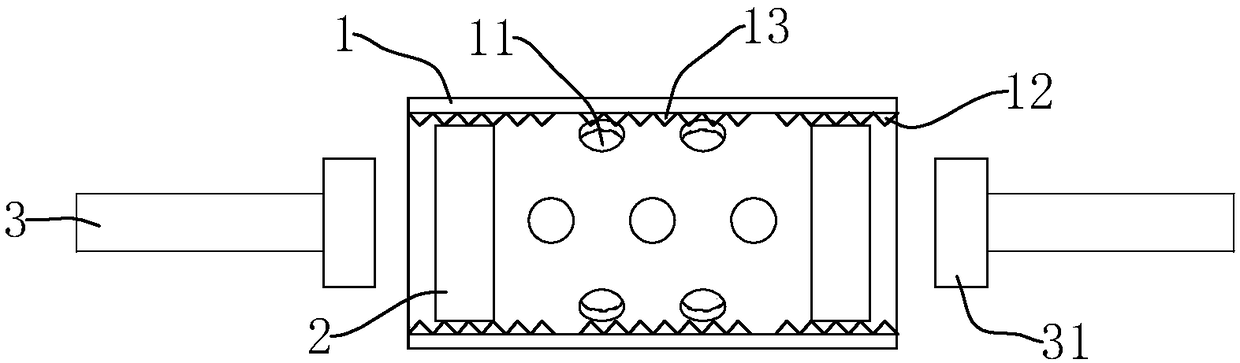
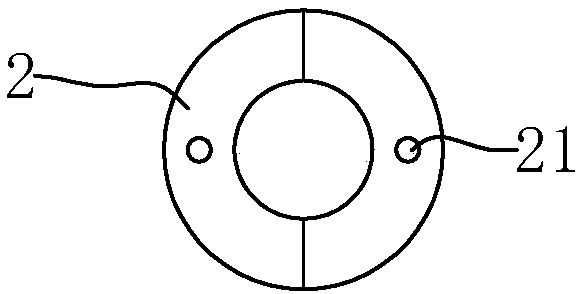
[0092] The snap-in connection device inside the sleeve and its connection structure, such as figure 1 As shown, the snap-fit connection device inside the sleeve 1 is the sleeve 1, and the sleeve 1 is provided with a grouting hole 11, which facilitates the flow of cement slurry into the inside of the sleeve 1 and fills the inner space of the sleeve 1 more easily during pouring. combine figure 2 , the internal clamping connection structure of the sleeve includes a sleeve 1, a clamping piece and a connecting rib, the clamping piece is an externally threaded nut 2, and the inner walls at both ends of the sleeve 1 are provided with internal threads for threaded connection of the externally threaded nut 2 12. The externally threaded nut 2 can be screwed and fixedly connected to the inside of both ends of the sleeve 1 through the internal thread 12 . Connecting bar is connecting reinforcing bar 3, and connecting reinforcing bar 3 is fixedly connected with expanding head 31 near ...
Embodiment 2
[0098] The snap-fit connection device inside the sleeve and its connection structure are different from Embodiment 1 in that, as Figure 4 As shown, the clamping member is an axially abutting retaining spring 4 , and the inner walls at both ends of the sleeve 1 are provided with engaging grooves 14 for engaging the axially abutting retaining spring 4 . combine Figure 5 , first extend the expansion head 31 into the inside of the sleeve 1, then set the axial abutment circlip 4 on the connecting steel bar 3, and then install the axial abutment circlip 4 in the snap-in groove 14, when When the expanding head 31 moves toward the direction of pulling out the sleeve 1 , it can abut against the axially abutting clip spring 4 to restrict the expanding head 31 from being pulled out of the sleeve 1 .
Embodiment 3
[0100] The snap-fit connection device inside the sleeve and its connection structure are different from Embodiment 2 in that, as Image 6 As shown, the inner ring of the axially abutting the circlip 4 is fixedly connected with the anti-off ratchet 41, the anti-off ratchet 41 is inclined toward the center of the sleeve 1 along the direction close to the central axis of the sleeve 1, and the expanding head 31 is inserted into the During the process of the sleeve 1, it abuts against the anti-off ratchet 41, and generates a force on the anti-off ratchet 41 in a direction away from the central axis of the sleeve 1, pushing the anti-off ratchet 41 to move away from the central axis of the sleeve 1. Elastic deformation, after the expansion head 31 passes through the axial abutment ring 4 , the detachment prevention ratchet 41 resumes deformation to limit the movement of the expansion head 31 toward the direction of pulling out the sleeve 1 .
[0101] combine Figure 7 , when the e...
PUM
 Abstract
Description
Claims
Application Information