Variable-flow speed-change brushless non-reversing permanent magnet direct-current motor

A DC motor, non-commutation technology, applied in electric components, magnetic circuit rotating parts, magnetic circuit and other directions, can solve the problems of high power consumption, poor motor speed regulation characteristics, high manufacturing cost, etc., to achieve power consumption Small volume, high utilization rate of permanent magnet energy, and fast torque response

Pending Publication Date: 2018-07-17
甘肃永动电子科技发展有限公司
View PDF0 Cites 0 Cited by
  • Summary
  • Abstract
  • Description
  • Claims
  • Application Information

AI Technical Summary

Problems solved by technology

[0003] The purpose of the present invention is to provide a brushless and commutated permanent magnet DC motor with variable current and variable speed, so as to solve the problems of poor speed regulation characteristics, large power consumption and high manufacturing cost of the existing motors

Method used


Image

  • Variable-flow speed-change brushless non-reversing permanent magnet direct-current motor
  • Variable-flow speed-change brushless non-reversing permanent magnet direct-current motor
  • Variable-flow speed-change brushless non-reversing permanent magnet direct-current motor

Examples


Embodiment 1

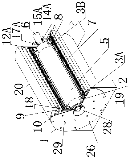
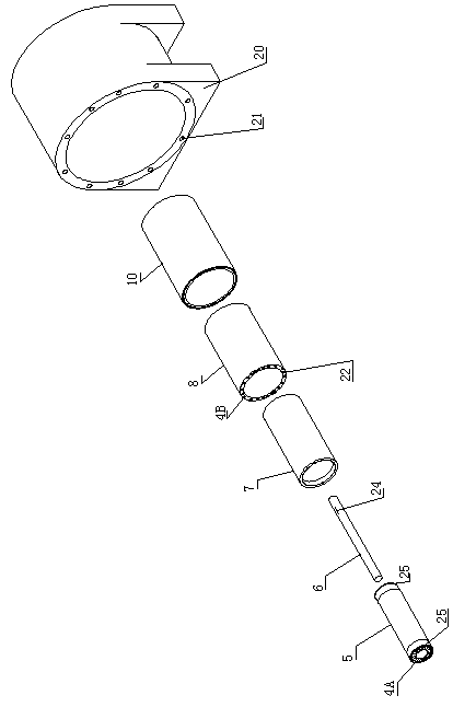
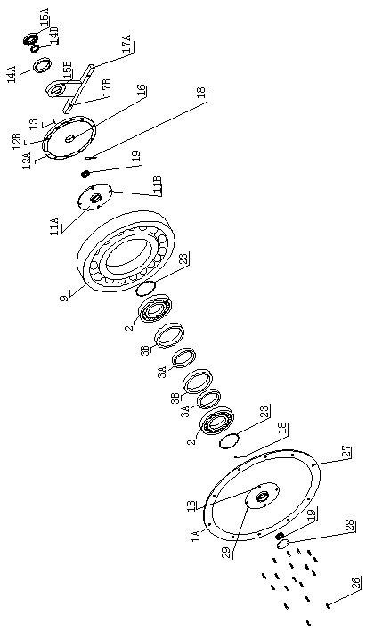
[0043] The present invention is designed according to the force that the energized wire will be subjected to in the magnetic field. The technical parameters of the inner and outer stator turns of the coil of the present invention are listed as columns; the radial diameter of the two ends of the outer stator (8) of the coil is 400mm, and its circumference is 1256mm, 66 wires can be arranged in the axial direction with a 19mm wire, the effective axial length of the wire in the magnetic field is 1000mm, and the wire diameter is 70mm 2 , the diameter of the wedge-shaped copper bar of the stator (5) inside the coil is 70 mm 2 , it only plays the role of conduction current. In order to reduce the resistance loss, its wire diameter can be increased, and the wire diameter of the conductive plate (18) is 70 mm 2 , the length is 100mm, and the magnetic induction of the permanent magnet inner and outer rotors is 0.3 Tesla. The total length of the current passing through the inner and ou...


PUM


Abstract

The invention discloses a variable-flow speed-change brushless non-reversing permanent magnet direct-current motor, and belongs to the field of direct current motors, aiming to solve the problems thatan existing motor is poor in speed regulation characteristic, large in power consumption and high in manufacturing cost. The variable-flow speed-change brushless non-reversing permanent magnet direct-current motor comprises a machine base, a permanent magnet inner rotor, a permanent magnet outer rotor, a coil inner stator and a coil outer stator, wherein a rotor shaft is arranged in the coil inner stator, a rotor shaft support bearing, and a permanent magnet magnetic suspension inner sleeve and a permanent magnet magnetic suspension outer sleeve that are in the same polarity are arranged at the right end of the rotor shaft, and the permanent magnet magnetic suspension inner sleeve is arranged in the permanent magnet magnetic suspension outer sleeve in a sleeved mode, a coil inner stator permanent magnet magnetic suspension inner sleeve is fastened in the outer diameter of the two ends of the coil inner stator in a sleeved mode, and the openings of the inner diameter of the two ends ofthe permanent magnet inner rotor are tightly sleeved with a coil inner stator permanent magnet magnetic suspension outer sleeve with the same polarity. The stator coil has the advantages of no iron core, no iron loss and high torque response, the utilization rate of the permanent magnetic energy is high, the power consumption is low, the variable speed is achieved through the variable flow, and the super-high speed operation can be achieved.

Description

technical field [0001] The invention belongs to the field of DC motors, and in particular relates to a variable-flow variable-speed brushless and commutation-free permanent magnet DC motor. Background technique [0002] DC motors are divided into radial magnetic field and axial magnetic field according to the magnetic field structure. The excitation method is divided into permanent magnet excitation and winding iron core excitation. They have one thing in common. Due to structural limitations such as size, the permanent magnet energy utilization rate of permanent magnet materials is low. For example, the DC permanent magnet synchronous drive motor of an electric vehicle has difficulty in weakening the magnetic field, poor speed regulation characteristics, low low-speed efficiency, difficulty in ultra-high-speed operation, complex motor drive control system, and commutation of the current, which consumes a lot of power. Manufacturing costs are high. Contents of the inventio...

Claims


Application Information

Patent Timeline
Patent Type & Authority Applications(China)
IPC IPC(8): H02K16/00H02K29/00H02K5/16H02K1/27H02K3/04
CPCH02K16/00H02K1/2706H02K1/2786H02K3/04H02K5/161H02K29/00
Inventor 马飞
Owner 甘肃永动电子科技发展有限公司
Why Eureka
Try Eureka