Steel plate cutting machine

A cutting machine, steel plate technology, applied in shearing devices, metal processing machinery parts, maintenance and safety accessories, etc., can solve the problems of cumbersome operation, large labor, short service life of cutting blades, etc., to achieve simple structure principle, reduce The effect of labor and life extension

Inactive Publication Date: 2018-07-20
吴晓丽
View PDF11 Cites 1 Cited by
  • Summary
  • Abstract
  • Description
  • Claims
  • Application Information

AI Technical Summary

Problems solved by technology

Today's steel plate cutting machines on the market are cumbersome to operate, require a lot of labor, and the service life of cutting blades is short.

Method used


Image

  • Steel plate cutting machine
  • Steel plate cutting machine

Examples


Embodiment Construction

[0018] The following will clearly and completely describe the technical solutions in the embodiments of the present invention with reference to the accompanying drawings in the embodiments of the present invention. Obviously, the described embodiments are only some, not all, embodiments of the present invention. Based on the embodiments of the present invention, all other embodiments obtained by persons of ordinary skill in the art without making creative efforts belong to the protection scope of the present invention.

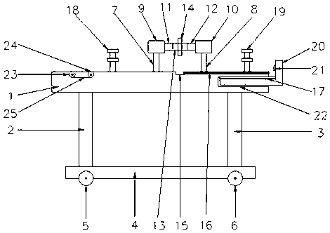
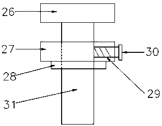
[0019] see Figure 1-2 , the present invention provides a technical solution: a steel plate cutting machine, including a cutting table 1, a base 4, a motor 13, a cutting blade 14, a cooling water tank 15, an L-shaped baffle 20 and a conveyor belt 25, and the middle part of the cutting table 1 is provided There are a first telescopic rod 7 and a second telescopic rod 8, the top of the first telescopic rod 7 is provided with a first cylinder 9, and the top of th...


PUM


Abstract

The invention discloses a steel plate cutting machine. The steel plate cutting machine comprises a cutting table, a base, a motor, a cutting blade, a cooling water groove, an L-shaped baffle plate, aconveying belt and a pressing plate; two extension rods are arranged at the middle part of the cutting table; cylinders are arranged on the extension rods; the motor is connected with the cylinders through support rods; the cutting blade is arranged on the motor; the cooling water tank is formed in the surface of the cutting table, and is positioned rightly below the cutting blade; fixing devicesare arranged at the two ends of the cutting table; a cavity is formed in the right side surface of the cutting table; an L-shaped baffle plate is inserted in the cavity; dividing rulers are arranged on the cutting table and the L-shaped baffle plate; two rotating shafts are arranged at the left end of the cutting table; the conveying belt sleeves the rotating shafts; the upper surface of the conveying belt is leveled with the cutting table; two brackets are arranged below the cutting table; the brackets are connected through the base; and two walking wheels are arranged on the base. The steelplate cutting machine is simple in structural principle and convenient to operate, can prolong the service life of the cutting device, and can reduce the labor amount of operators.

Description

technical field [0001] The invention relates to the technical field of cutting machines, in particular to a steel plate cutting machine. Background technique [0002] With the development of the modern mechanical processing industry, the requirements for cutting quality and precision are constantly improving, and the requirements for improving production efficiency, reducing production costs, and highly intelligent automatic cutting functions are also increasing. The development of CNC cutting machines must adapt to the requirements of the development of modern machining industry. Cutting machine is divided into flame cutting machine, plasma cutting machine, laser cutting machine, water cutting and so on. The laser cutting machine has the fastest efficiency, the highest cutting precision, and the cutting thickness is generally small. The cutting speed of the plasma cutting machine is also very fast, and the cutting surface has a certain slope. The flame cutting machine is...

Claims


Application Information

Patent Timeline
Patent Type & Authority Applications(China)
IPC IPC(8): B23D19/00B23D33/02B23D33/12B23Q11/10
CPCB23D19/00B23D33/02B23D33/12B23Q11/10
Inventor 吴晓丽
Owner 吴晓丽
Why Eureka
Try Eureka