Novel wire harness contact injection molding strip transfer mechanism

A wire harness and mold strip technology, which is applied in the field of new wiring harness contact injection molding mold strip operation mechanism, can solve the problems of increased space occupied by production equipment, high requirements for workshop space, and huge equipment, and achieve a reasonable layout effect

Pending Publication Date: 2018-07-20
东莞市星洁电器五金有限公司
View PDF6 Cites 3 Cited by
  • Summary
  • Abstract
  • Description
  • Claims
  • Application Information

AI Technical Summary

Problems solved by technology

[0004] However, for mold strips, which are large in size and require precise rigid equipment, the use of conveyor belts or conveyor chains can only be used for straight-line operation, or for curved transmission with a large turning radius (turning radius of more than 10 for the size of the transported items), the conveyor belt is arranged in a straight line It is impossible to directly complete the operation of the mold strips, and it is necessary to add a set of manipulators to assist the mold strips from the unloading station. The increase in the manipulator greatly increases the cost; The equipment is huge, and the space requirements for the factory building are high, which reduces the space utilization rate of the factory building. For urban areas where every inch of land is expensive, the transitional occupation of the factory building space also increases the production cost invisibly.
[0005] The multi-station circular turntable transmission equipment is arranged in a circle. For example, a four-station circular turntable machine arranges a station every 90 degrees. The loading station, injection station and unloading station are located in three Different orientations greatly increase the size of the production line in the width direction, and the occupied space of the entire production equipment increases; in addition, when the size of the produced wire harness is long, the phenomenon of wire harness winding often occurs when the circular turntable machine rotates. To solve this problem, it is necessary to It is necessary to add a winding station before loading the material. First, the long wire bundles are bundled and then loaded. This adds a winding device and increases the size and cost of the entire production line.

Method used


Image

  • Novel wire harness contact injection molding strip transfer mechanism
  • Novel wire harness contact injection molding strip transfer mechanism
  • Novel wire harness contact injection molding strip transfer mechanism

Examples


Embodiment

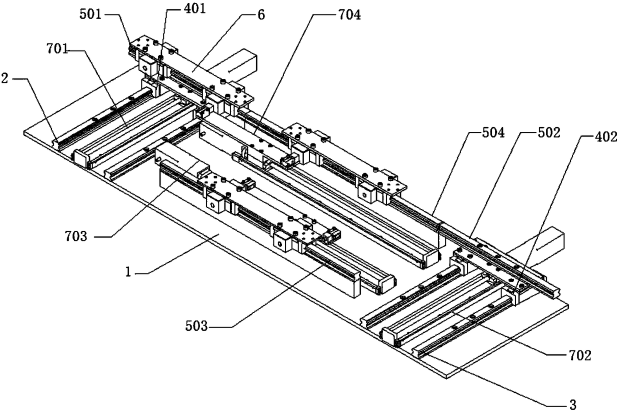
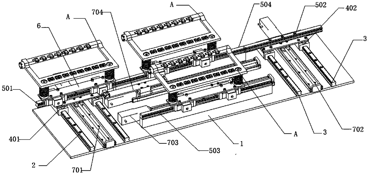
[0033] see figure 1 , figure 2 , image 3 , Figure 4 , Figure 5 , Image 6 , Figure 7 , Figure 8 , Figure 9 , Figure 10 , Figure 11 , Figure 12 , Figure 13 , a new type of wire harness contact injection molding operating mechanism provided by the embodiment of the present invention, such as figure 1 , figure 2 As shown, the mechanism includes a rectangular bottom plate 1, and the rectangular bottom plate 1 is used to carry various components;

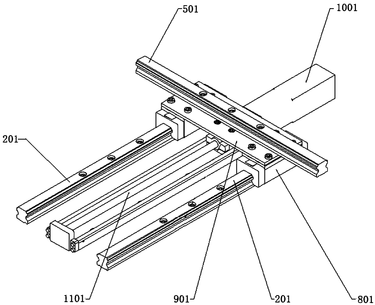
[0034] The first longitudinal sliding rail group 2 and the second longitudinal sliding rail group 3 are vertically arranged, the first longitudinal sliding rail group 2 includes two first longitudinal sliding rails 201 vertically arranged on the rectangular bottom plate 1, two The first longitudinal slide rails 201 are respectively connected to the first longitudinal slide assemblies 401, the upper part of the first longitudinal slide assemblies 401 is fixedly connected with the first transverse slide rails 501, ...


PUM


Abstract

The invention discloses a novel wire harness contact injection molding strip transfer mechanism. The mechanism comprises a rectangular baseplate used for bearing components; a first longitudinal sliding rail group and a second longitudinal sliding rail group which are arranged longitudinally, and a third transverse sliding rail, a fourth transverse sliding rail, a third driving component and a fourth driving component which are arranged on the rectangular baseplate transversely. The transfer mode of the novel wire harness contact injection molding strip transfer mechanism is a planar rectangular transfer mode, and a feeding station, an injection station and a discharging station are arranged on one straight line; only one transit station is not located on the straight line, and has littleinfluence on the longitudinal dimension of a production line, so that the layout of production equipment is more reasonable. Four single-module screw guide driving mechanisms are applied, and throughcooperative application of the driving mechanisms, the transfer of a molding strip in a small flat space is finished; and the transfer mechanism has the advantages of short transport route, high transfer efficiency, no need of additional equipment, simple structure and cost saving.

Description

technical field [0001] The invention relates to the field of equipment for injection molding of technical contacts, in particular to a novel operating mechanism for injection molded strips of wire harness contacts. Background technique [0002] The mold strip operation system is a key component of the equipment for the automatic production of wire harnesses. The improvement of its operating efficiency plays a vital role in the production efficiency of the entire automatic production equipment for wire harnesses. The reliability of the operating equipment restricts the reliability of the entire automated production equipment. sex. [0003] Existing operating equipment all adopts the form of circular turntable, conveyer belt or conveyer chain. [0004] However, for mold strips, which are large in size and require precise rigid equipment, the use of conveyor belts or conveyor chains can only be used for straight-line operation, or for curved transmission with a large turning r...

Claims


Application Information

Patent Timeline
Patent Type & Authority Applications(China)
IPC IPC(8): B29C45/17B29C31/00
CPCB29C31/00B29C45/17
Inventor 黄开朗方继根吴进军王西峰胡玉辉舒豪刘晓华
Owner 东莞市星洁电器五金有限公司
Why Eureka
Try Eureka