
A continuous fiber 3D printing device and method

A 3D printing and continuous fiber technology, which is applied in the field of composite material manufacturing, can solve problems such as incompatibility, high toughness, and low strength, and achieve the effect of reducing the probability of fiber damage, reducing the risk of degradation, and maintaining structure and performance

Active Publication Date: 2020-08-04
AEROSPACE INST OF ADVANCED MATERIALS & PROCESSING TECH
View PDF1 Cites 4 Cited by
  • Summary
  • Abstract
  • Description
  • Claims
  • Application Information

AI Technical Summary

Problems solved by technology

[0003] At this stage, thermoplastic resin printing technology is still based on pure resin or thermoplastic resin with reinforced particles. The material has high toughness, low modulus, and low strength, which cannot meet the requirements of aerospace parts.
In order to improve the mechanical bearing capacity of the material, research institutions at home and abroad have developed melt-printed continuous fiber parts; however, in this process, the high-viscosity resin is difficult to completely soak the "dry" fiber, which affects the internal quality and appearance quality of the product; at the same time , some resins that are easy to oxidize and degrade are not suitable for the method of fusion printing

Method used


Image

  • A continuous fiber 3D printing device and method
  • A continuous fiber 3D printing device and method

Examples


Embodiment Construction

[0024] Specific embodiments of the present invention will be described in detail below in conjunction with the accompanying drawings. In the following description, for purposes of explanation and not limitation, specific details are set forth in order to provide a thorough understanding of the invention. It will be apparent, however, to one skilled in the art that the present invention may be practiced in other embodiments that depart from these specific details.

[0025] It should be noted here that, in order to avoid obscuring the present invention due to unnecessary details, only the device structure and / or processing steps closely related to the solution according to the present invention are shown in the drawings, and the steps related to the present invention are omitted. Invent other details that don't really matter.

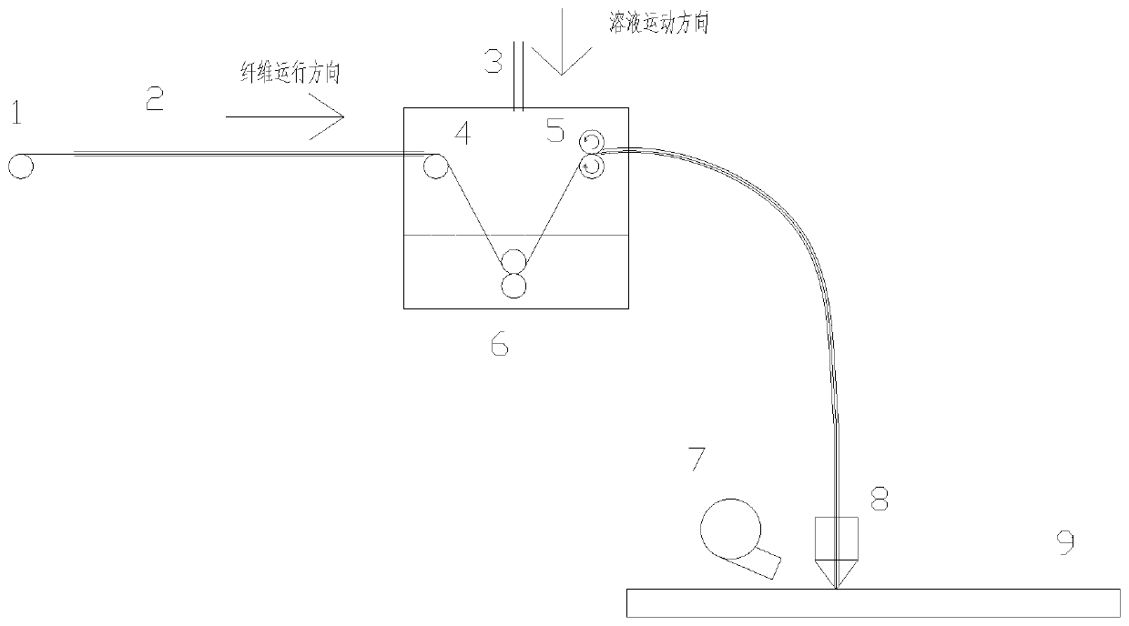
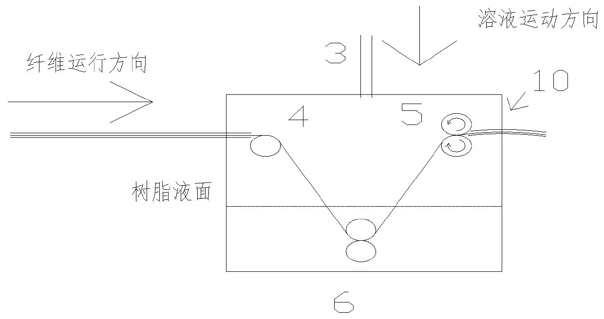
[0026] see figure 1 , this embodiment provides a continuous fiber 3D printing device, including:

[0027] Fiber roller 1, dipping part and printing pa...


PUM

PropertyMeasurementUnit
viscosityaaaaaaaaaa

Abstract

The invention provides a continuous fiber 3D printing device and a continuous fiber 3D printing method. The continuous fiber 3D printing device comprises a fiber roller, a gumming part and a printingpart; the gumming part is provided with a housing injected with a resin solution; a tension roller, a gumming opposite-opening roller and a traction roller are sequentially arranged in the housing; the tension roller is arranged above a liquid level of the resin solution and is used to provide dry fiber with a part of pre-tightening force by the action of frictional force; the gumming opposite-opening roller is arranged below the liquid level of the resin solution; the gumming opposite-opening roller and the tension roller form an included angle; the traction roller is arranged above the liquid level of the resin solution and is used to provide traction force; and the dry fiber enters into the gumming part through the fiber roller, is gummed by the tension roller, the gumming opposite-opening roller and the traction roller sequentially, and then is printed by the printing part. The intensity of an obtained workpiece is improved by more than 4 times compared with that of a workpiece in3D printing of existing resin, so that a foundation is laid for high-performance printing components applied to the aerospace field.

Description

technical field [0001] The invention relates to a continuous fiber 3D printing device and method, belonging to the technical field of composite material manufacturing. Background technique [0002] 3D printing technology, also known as additive manufacturing, is a technology that adds materials layer by layer through printing equipment to manufacture three-dimensional objects based on a pre-designed three-dimensional model. This technology integrates cutting-edge technologies in the fields of digital modeling technology, electromechanical control technology, information technology, material science and chemistry. It is a kind of rapid prototyping technology and is known as the core technology of the "third industrial revolution". Among them, the printing technology of thermoplastic resin is the main component, which has been developed and applied in the fields of automobile, medicine, food, etc., and has become one of the hot spots pursued by domestic and foreign counterpart...

Claims


Application Information

Patent Timeline
Patent Type & Authority Patents(China)
IPC IPC(8): B29C64/118B29C64/176B29C64/20B29C64/209B29C64/255B29C64/295B29C64/314B33Y10/00B33Y30/00B33Y40/00B33Y40/10
CPCB33Y40/00
Inventor 毕向军王红丽缪伟民朱伟杰
Owner AEROSPACE INST OF ADVANCED MATERIALS & PROCESSING TECH
Learn More