Large field of view scanning system

A technology of scanning system and large field of view, applied in the field of large field of view scanning system, can solve problems such as space limitation, and achieve the effect of large variation range, reduced installation and adjustment requirements, and obvious innovation and practicability.

Inactive Publication Date: 2018-07-20
SANMING UNIV
View PDF5 Cites 2 Cited by
  • Summary
  • Abstract
  • Description
  • Claims
  • Application Information

AI Technical Summary

Problems solved by technology

Among them, the tip-tilt single-mirror scanning technology is usually driven by piezoelectric ceramics, but its placement has strict space restrictions and must be placed on the pupil plane

Method used


Image

  • Large field of view scanning system
  • Large field of view scanning system

Examples


Embodiment Construction

[0021] In order to make the purpose, technical solutions and advantages of the embodiments of the present invention clearer, the technical solutions in the embodiments of the present invention will be clearly and completely described below in conjunction with the accompanying drawings in the embodiments of the present invention. Obviously, the described embodiments It is some embodiments of the present invention, but not all of them. Based on the implementation manners in the present invention, all other implementation manners obtained by persons of ordinary skill in the art without creative efforts fall within the protection scope of the present invention. Accordingly, the following detailed description of the embodiments of the invention provided in the accompanying drawings is not intended to limit the scope of the claimed invention, but merely represents selected embodiments of the invention. Based on the implementation manners in the present invention, all other implement...


PUM


Abstract

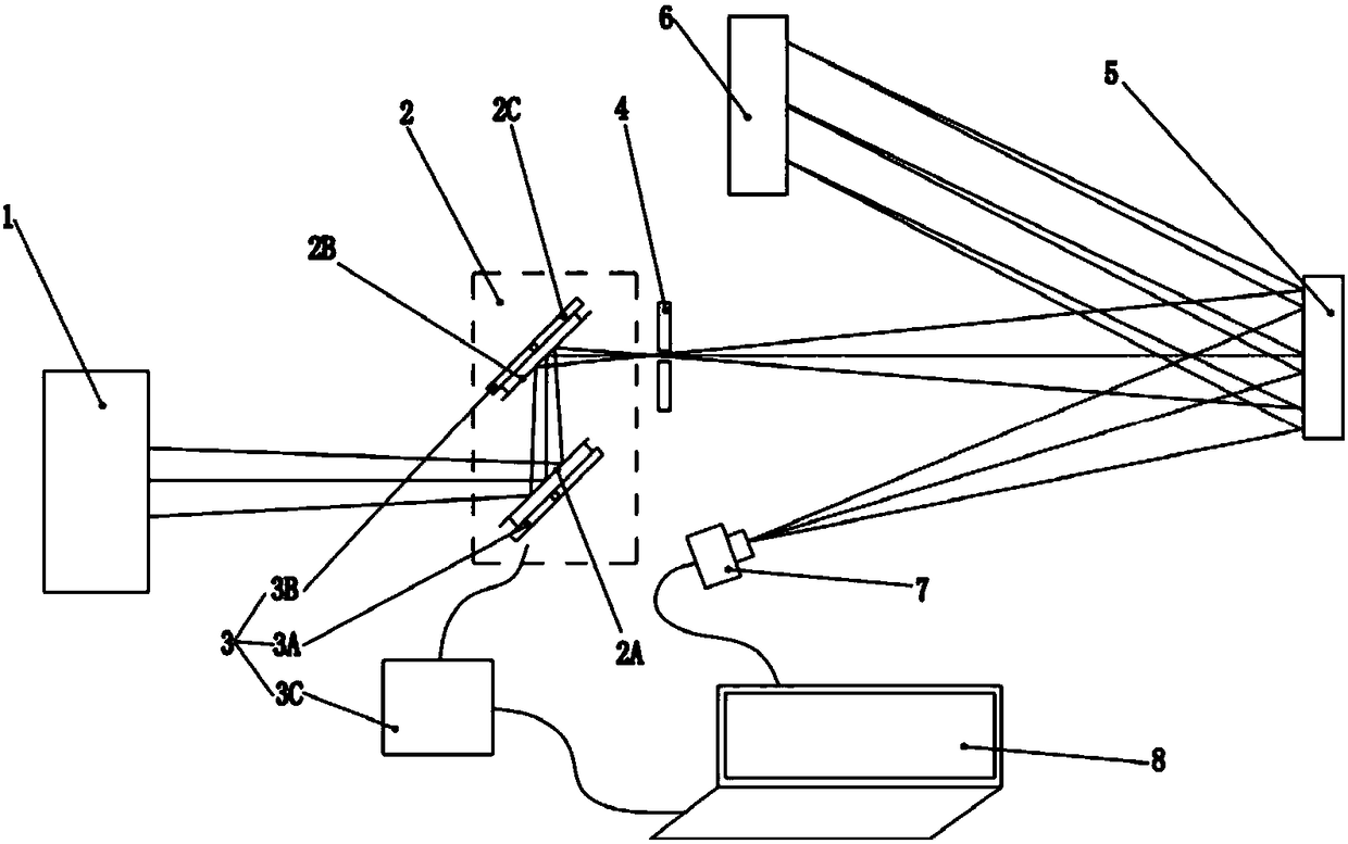
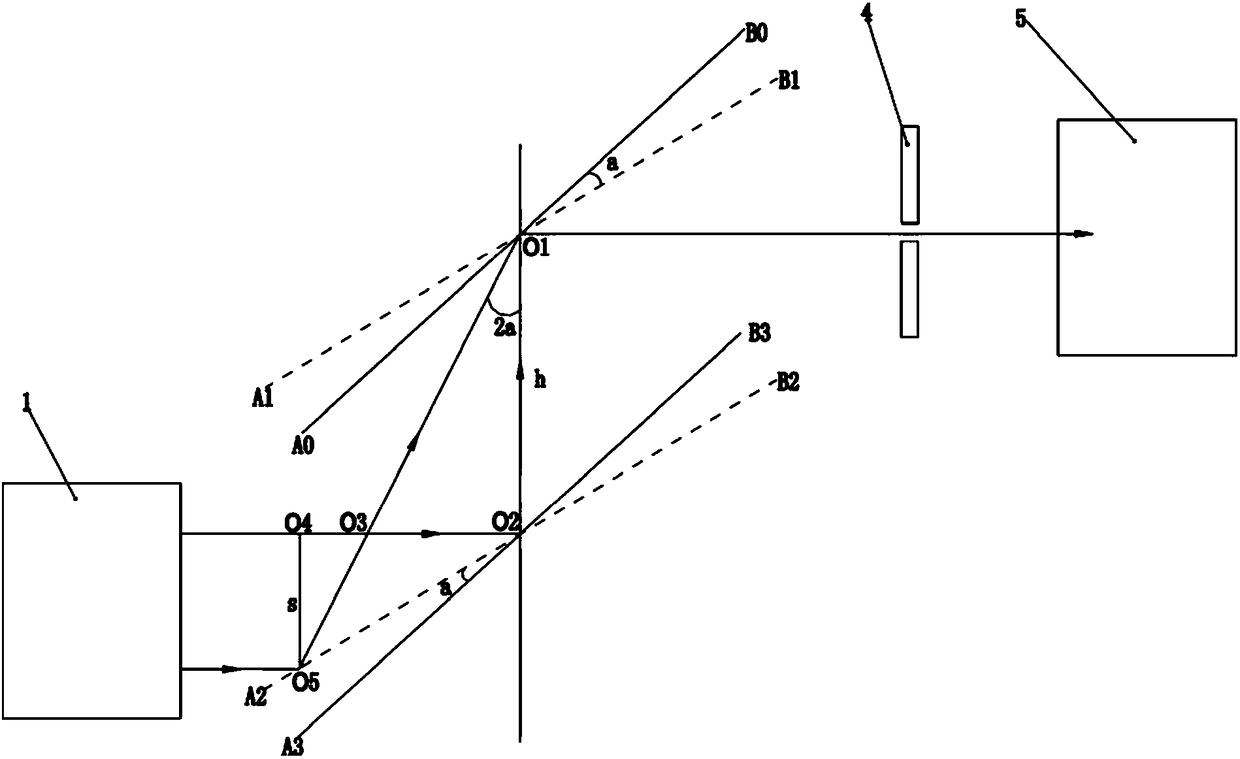
The invention relates to a large field of view scanning system which comprises a solar optical telescope, a field of view scanning device, a rotary drive mechanism, a grating spectrometer, a CCD camera and a computer. The grating spectrometer is provided with a slit part, a collimating mirror and a grating part. The field of view scanning device comprises two parallel plane mirrors. The rotary drive mechanism is used for driving two plane mirrors to rotate synchronously. The solar optical telescope is used for collecting light beams emitted by a solar atmospheric moving target, and the collected light beams are sequentially reflected by two plane mirrors and then enter the slit part. The light beams come into the collimating mirror through the slit part, and the collimated light beam comeinto the grating part. The CCD camera is used to collect the light beams re-come into the collimating mirror and convert the light beams into an electrical signal. The computer is used to form corresponding spectral information according to the electrical signal. According to the large field of view scanning system provided by the invention, the field of view scanning device adopts the field of view scanning mode of double plane mirrors; the structure of the optical system is simplified; and the installation requirements of the optical system are reduced.

Description

technical field [0001] The present invention relates to an optical scanning device, in particular to a large field of view scanning system. Background technique [0002] The slit-type grating spectrometer is an important instrument for studying the distribution of the solar magnetic field, and it has been widely used in the observation of the solar atmosphere. Huang Youran, Xu Aoao, and Qin Zhihai were included in the "Measured Astrophysics" published by Beijing Science Press in 1987. Related technical information published by et al. [0003] In order to study the distribution characteristics of the solar magnetic field in different solar atmospheres, three-dimensional spectral imaging technology is usually used. Three-dimensional spectral imaging technology can be divided into field integration unit (IFU) technology based on optical fiber array, image cutter technology and field scanning technology (Wang Junfan, Zhu Yongtian, Hu Zhongwen. Three-dimensional astronomical ima...

Claims


Application Information

Patent Timeline
Patent Type & Authority Applications(China)
IPC IPC(8): G01J3/28
CPCG01J3/2823
Inventor 郑联慧魏茂金颜慧贤
Owner SANMING UNIV
Why Eureka
Try Eureka