Automatic construction equipment of power cable

A technology for power cables and construction equipment, applied in the field of cable repair equipment, can solve problems such as long time consumption, unstable connection between cables and copper pipes, and low work efficiency

Inactive Publication Date: 2018-07-20
丁佐琳
View PDF0 Cites 12 Cited by
  • Summary
  • Abstract
  • Description
  • Claims
  • Application Information

AI Technical Summary

Problems solved by technology

[0003] In order to solve the above problems, the present invention provides an automatic construction equipment for power cables, which can solve the existing problems in the process of manually repairing the cables, such as the need to manually process the insulator on the surface of the cables, and the need to manually pull the cables for transportation. Picking and placing copper pipes for docking, manual processing of cable surface insulators requires selection of corresponding processing tools according to the size of the cables, cables of different sizes require manual selection of corresponding processing tools, the operation is complicated, and manual pulling of the cables is labor-intensive , the manual control of the connection between the cable and the copper pipe is unstable, and the gap between the cable and the inner size of the copper pipe is small during the connection process, which makes manual connection difficult, time-consuming and low in efficiency; it can realize damaged cables The function of automatic docking of copper pipes in the process of line repair does not require manual operation. It automatically controls the docking of copper pipes and cables, which is less difficult to connect, and has the advantages of good stability, simple operation, low labor intensity and high work efficiency.

Method used


Image

  • Automatic construction equipment of power cable
  • Automatic construction equipment of power cable
  • Automatic construction equipment of power cable

Examples


Embodiment Construction

[0027] In order to make the technical means, creative features, goals and effects achieved by the present invention easy to understand, the present invention will be further described below in conjunction with specific illustrations.

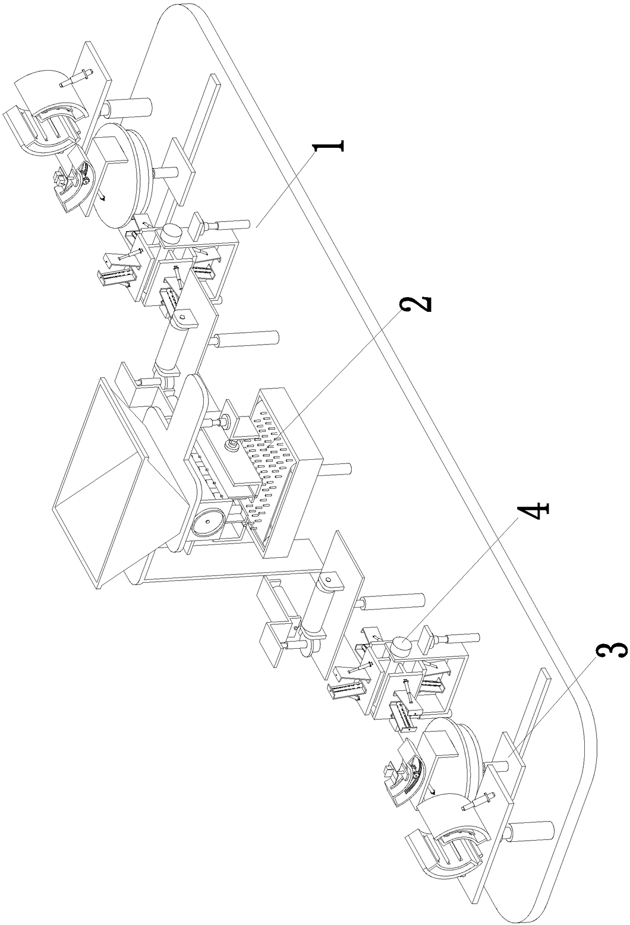
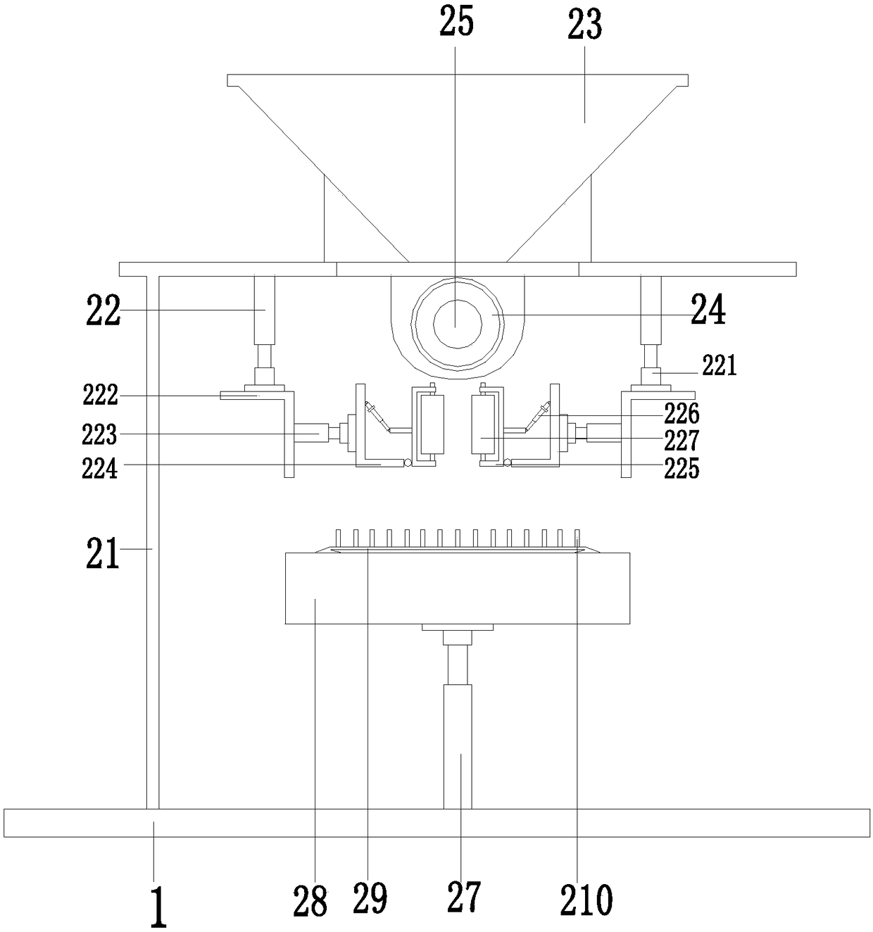
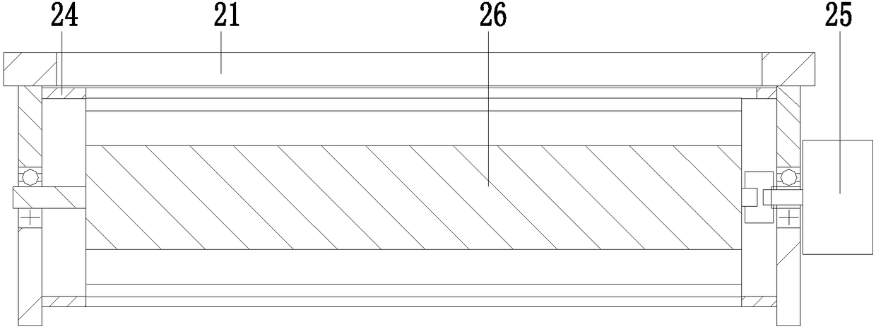
[0028] Such as Figure 1 to Figure 7 As shown, a power cable automatic construction equipment includes a base plate 1, a casing device 2 is installed in the middle of the upper end of the base plate 1, and two cable surface treatment devices 3 are installed on the base plate 1, and the two cable surface treatment devices 3 are located symmetrically. On the outer sides of the front and rear ends of the bottom plate 1, two cable delivery devices 4 are installed on the bottom plate 1, and the two cable delivery devices 4 are symmetrically located on the inner sides of the front and rear ends of the bottom plate 1, and the two cable surface treatment devices 3 can treat the surface of the cable that needs to be repaired. processing, the two cable co...


PUM


Abstract

The invention relates to automatic construction equipment of a power cable. The automatic construction equipment comprises a bottom plate, wherein a sleeve device is arranged at a middle part of an upper end of the bottom plate, two cable surface processing devices are arranged on the bottom plate, the two cable surface processing devices are symmetrically arranged at outer sides of a front end and a rear end of the bottom plate, and two cable transmission devices are arranged on the bottom plate and are symmetrically arranged at inner sides of the front end and the rear end of the bottom plate. By the automatic construction equipment, the problems that an insulator on a surface of the cable is needed to be processed by manual during the existing cable recovery process by manual, the cableis needed to be pulled and transmitted by manual, a copper pipe is needed to be taken and placed for abutting, a corresponding processing tool is needed to be selected according to the size of the cable during manual processing insulator on the surface of the cable, the corresponding processing tool is needed to be selected with regard to cables with different sizes, the operation is complicated,manual cable control and copper pipe abutting are not stable and a gap between the cable and the internal size of the copper pipe during the abutting process is relatively small are solved.

Description

technical field [0001] The invention relates to the technical field of cable repair equipment, in particular to automatic construction equipment for power cables. Background technique [0002] Cables include power cables, control cables, compensation cables, shielded cables, high-temperature cables, computer cables, signal cables, coaxial cables, fire-resistant cables, marine cables, mining cables, aluminum alloy cables, etc. They are all composed of single-strand or multi-strand wires and insulation layers, used to connect circuits, electrical appliances, etc. The manufacture of wires and cables is completely different from the production of most electromechanical products. Mechanical and electrical products are usually assembled into components, and multiple components are assembled into a single product, and the product is measured by the number of units or pieces. Wire and cable are based on length as the basic unit of measurement. All wires and cables start from condu...

Claims


Application Information

Patent Timeline
Patent Type & Authority Applications(China)
IPC IPC(8): H02G1/16H02G1/12
CPCH02G1/16H02G1/1256
Inventor 丁佐琳
Owner 丁佐琳
Why Eureka
Try Eureka