Medical orthopedic steel plate with controllable continuous locking and pressurizing functions

A steel plate and orthopaedic technology, applied in the field of new orthopaedic steel plates, can solve the problems of inability to ensure compression and closure, inability to pressurize the fracture end, and increase the fracture gap, so as to maintain the length of the bone, ensure stress stimulation, and promote fracture healing. Effect

Inactive Publication Date: 2018-07-24
张强
View PDF7 Cites 4 Cited by
  • Summary
  • Abstract
  • Description
  • Claims
  • Application Information

AI Technical Summary

Problems solved by technology

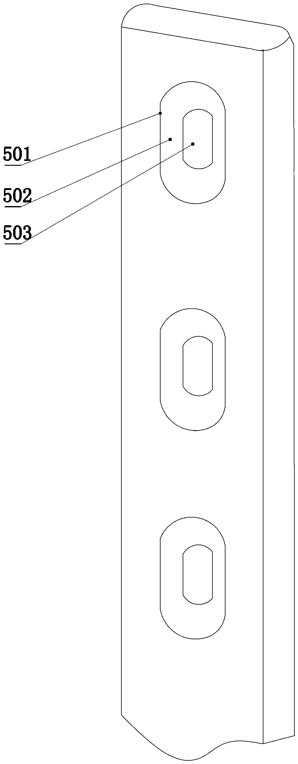
However, in the treatment of limb fractures, only one-time pressure reduction can be performed during the operation. After the locking nail is fixed, the screw is relatively static relative to the fracture end, and continuous pressure cannot be applied to the fracture end.
This makes it easy to cause bone nonunion due to increased fracture gap

Method used


Image

  • Medical orthopedic steel plate with controllable continuous locking and pressurizing functions
  • Medical orthopedic steel plate with controllable continuous locking and pressurizing functions
  • Medical orthopedic steel plate with controllable continuous locking and pressurizing functions

Examples


Embodiment 1

[0030] All the screws 3 at both ends of the steel plate are installed on the sliding pressure pad 2 which can slide to realize sliding pressure.

[0031] When in use, all sliding compression pads 2 should be installed at the far end of the compression chute, such as Image 6 As shown, the upper or lower end surface of the sliding pressing pad is in close contact with the upper or lower end surface of the pressing chute 5. The distal end refers to the end of the compression chute away from the fracture site 7. Such as Figure 5 During the operation, a one-time compression reduction is adopted during the operation, and steel plate is used for fixation; after the bone resorption of the fractured end after the operation, the sliding compression pad will slide towards the fracture site under the action of muscle tissue tension or body gravity compression.

[0032] It should be noted that the aforementioned pressing distance should be equal to the sum of the sliding gaps of the upper and ...

Embodiment 2

[0034] All the screws 3 at one end (upper end or lower end) of the upper and lower ends are installed on the pressure chute 5 by sliding the pressure pad 2.

[0035] The usage method is basically the same as in the first embodiment. All sliding compression pads 2 should be installed at the far end of the compression chute. The upper end surface of the sliding pressing pad is in close contact with the upper end surface of the pressing chute 5. During the operation, a one-time compression reduction was used during the operation, and plate fixation was adopted; after the bone resorption of the fractured end occurred after the operation, the screw 3 in the screw mounting hole 6 could not move under the action of the muscle tissue tension or the gravity pressure of the body, and the bones caused the sliding increase. The pressure pad will slide towards the fracture site.


PUM


Abstract

The invention discloses a medical orthopedic steel plate with controllable continuous locking and pressurizing functions. According to the technical scheme, the medical orthopedic steel plate comprises a steel plate body and screws. The screws are installed at the upper end and the lower end of the steel plate body, all the screws at one end or all the screws on the steel plate body are installedon pressurizing sliding grooves through sliding pressurizing cushion blocks, the sliding pressurizing cushion blocks are detachably connected with the screws, and the pressurizing sliding grooves areformed in the longitudinal direction of the steel plate body. After the sliding pressurizing cushion blocks are installed in place, longitudinal sliding gaps of the sliding pressurizing cushion blocksare formed in the pressurizing sliding grooves. The medical orthopedic steel plate is simple in structure and convenient to implement. According to the technical scheme, it is only needed to change original screw holes in one end of the steel plate body into the pressurizing sliding grooves, and the screws are installed on the sliding pressurizing cushion blocks. The sliding pressurizing cushionblocks can freely slide up and down along the pressurizing sliding grooves. After fracture end bone resorption exists after an operation, under the muscular tissue tension or body gravity pressurizingeffect, the sliding pressurizing cushion blocks can slide to a fracture part.

Description


Claims


Application Information

Patent Timeline
Owner 张强
Why Eureka
Try Eureka