
Light beam phase modulation and direction adjustment device

A phase modulation and direction modulation technology, applied in optics, optical components, instruments, etc., can solve the problems of low precision, complex optical synthetic aperture common phase method, etc., and achieve low cost, important technical value and economic value, and simple structure. Effect

Pending Publication Date: 2018-07-24
NANJING UNIV OF POSTS & TELECOMM
View PDF0 Cites 4 Cited by
  • Summary
  • Abstract
  • Description
  • Claims
  • Application Information

AI Technical Summary

Problems solved by technology

[0003] The purpose of the present invention is to: aim at the defects existing in the prior art, to propose a light beam phase modulation and direction adjustment device and its use method, which are used to solve the problems of the existing optical synthetic aperture common phase method, such as complexity and low precision, and make the common phase Simplify the process and reduce the common phase error

Method used


Image

  • Light beam phase modulation and direction adjustment device
  • Light beam phase modulation and direction adjustment device

Examples


Embodiment 1

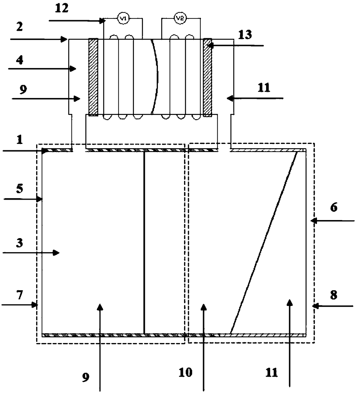
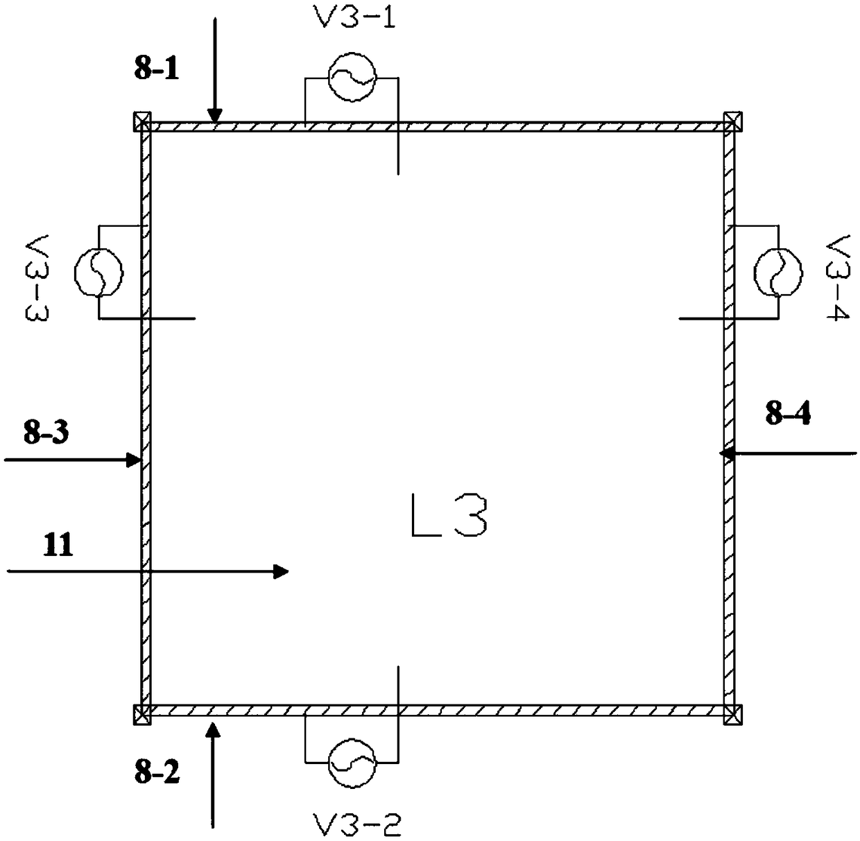
[0029] The phase-modulating cavity is made of metal round tube, and the inner wall is coated with Teflon film; the inner chip where the direction-tuning cavity is located uses the same metal tube as the above-mentioned phase-modulating cavity, which is cut into 4 parts on average along the axial direction and leads out electrodes , and then use epoxy resin to bond them together, coat the inner wall with evaporated 3-10μm Parylene insulating dielectric material, and then coat a very thin layer of Teflon@1600, and set the voltage V3-1~V3- 4 Applied to the above four electrodes respectively; use a soft plastic round tube to make the driving inner core and package it, open a hole in the left part of the first liquid in the phase-modulating chamber, open a hole at the left end of the driving inner core, and use a thin tube to connect the two holes To connect, open a hole near the middle of the second liquid in the phase adjustment chamber, open a hole at the right end of the driving...

Embodiment 2

[0034] The phase adjustment cavity is made of plastic hard round tube, which is convenient for industrial scale production. Because the plastic itself has hydrophobic properties, a layer of grease is coated on its inner wall; the inner chip where the adjustment cavity is located is made of the same plastic as the above phase adjustment cavity. The hard round tube is evenly plated with 4 pieces of tile-shaped metal nickel on its inner wall and leads to 4 electrodes, and the inner wall is coated with 3-10μm parylene insulating dielectric material, and then coated with a very thin layer Teflon@1600, and set the voltage V 3-1 ~V 3-4Applied to the above four electrodes respectively; use PDMS to make the driving inner core and package it, open a hole in the left part of the first liquid in the phase modulation chamber, open a hole at the left end of the driving inner core, and use a thin tube to connect the two holes, A hole is opened near the middle of the second liquid in the pha...

Embodiment 3

[0039] The phase-modulating cavity is made of hardened silicone rubber round tube, which is convenient for industrial scale production. Since the silicone rubber itself has hydrophobic properties, a layer of grease is coated on its inner wall; The same hardened silicone rubber round tube is evenly plated with 4 tile-shaped silicone rubber made of conductive silicone rubber on its inner wall and leads to 4 electrodes, then bonded with PDMS, and then evaporated on its inner wall 1-10μm PDMS insulating dielectric material, then coated with a very thin layer of Teflon@1600, and set the voltage V 3-1 ~V 3-4 Applied to the above four electrodes respectively; use PDMS to make the driving inner core and package it, open a hole in the left part of the first liquid in the phase modulation chamber, open a hole at the left end of the driving inner core, and use a thin tube to connect the two holes, Open a hole near the middle of the second liquid in the phase adjustment chamber, drive th...


PUM


Abstract

The invention relates to a light beam phase modulation and direction adjustment device and a use method thereof. The light beam phase modulation and direction adjustment device comprises a function inner core and a drive inner core which are connected with each other through a micro-channel; the function inner core and symmetrically-arranged left and right cover plates form a function cavity composed of a phase modulation cavity and a direction adjustment cavity; three liquid materials which are mutually insoluble and have different refractive indexes are respectively placed in the phase modulation cavity and the direction adjustment cavity, and a phase modulation liquid column and a direction adjustment liquid column are formed by the respective combination of the liquid materials. The light beam phase modulation and direction adjustment device and the use method thereof provided by the invention have the benefits that through applying pressure onto the left side of the drive inner core, the filling ratio of the first liquid to the second liquid in a drive cavity is changed, and the phase difference of a light beam propagated from left to right is changed, so that the phase modulation is finished; through controlling the voltages of four conductive material electrodes in the direction adjustment cavity, the direction in which the light beam is propagated from left to right iscontrolled, and a two-dimensional adjustable plane is realized, so that the direction adjustment is finished. The combined phase modulation and direction adjustment functions are in the same device, so that the problem of difficult common phase of an optical synthetic aperture is solved, therefore, the common phase process is simplified, and the common phase error is reduced.

Description

technical field [0001] The invention relates to a light beam phase-modulation and direction-regulation device and a method for using the same, and belongs to the technical fields of optical synthetic aperture, photoelectric information integration device, microfluidic optical analysis and self-adaptive optics. Background technique [0002] Optical synthetic aperture technology is to arrange multiple small-aperture optical mirrors or optical systems according to a certain spatial position, through the adjustment of optical paths and mirrors and phase matching, so that the beams passing through each sub-aperture meet the same phase requirements on the common focal plane. In order to realize the coherent superposition of the light field, the diffraction resolution of a single large-aperture system equivalent to the light aperture can be achieved. At present, the optical synthesis aperture technology has become an important means to increase the aperture of the telescope and imp...

Claims


Application Information

Patent Timeline
Patent Type & Authority Applications(China)
IPC IPC(8): G02B26/06G02B26/08
CPCG02B26/06G02B26/08
Inventor 陈陶徐正祥李飞燕梁忠诚赵瑞孔梅梅徐荣青谌静
Owner NANJING UNIV OF POSTS & TELECOMM
Learn More