Cable insulation layer coating machine

A cable insulation and coating machine technology, applied in the direction of conductor/cable insulation, cable/conductor manufacturing, circuit, etc., can solve the problems of uniform insulation layer, not smooth and uniform, copper wire eccentricity, etc., to achieve low cost, wrapping Even and smooth effect

Active Publication Date: 2018-07-24
重庆博创知识产权运营有限公司
View PDF8 Cites 6 Cited by
  • Summary
  • Abstract
  • Description
  • Claims
  • Application Information

AI Technical Summary

Problems solved by technology

The above-mentioned device has the following defects: 1. Due to the different extrusion pressures of the insulating glue in the wire-passing channel, it is difficult to completely cover the copper wires, resulting in that the outer diameter of the obtained insulating layer cannot match the inner diameter of the outlet end of the wire-passing channel. 2. The mol

Method used


Image

  • Cable insulation layer coating machine

Examples


Embodiment Construction

[0018] The following is further described in detail through specific implementation methods:

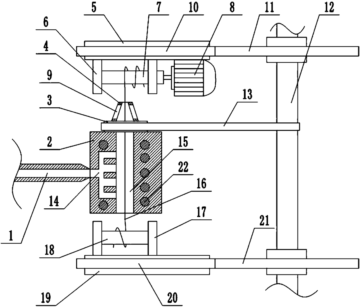
[0019] The reference signs in the drawings of the description include: extruder 1, mold 2, base 3, scraper seat 4, first turntable 5, first bump 6, first sleeve 7, first motor 8, strip Through hole 9, first driven gear 10, first driving gear 11, rotating shaft 12, belt 13, glue chamber 14, wire passage 15, copper wire 16, second bump 17, second sleeve 18, second Two turntables 19, a second driven gear 20, a second driving gear 21, and a heater 22.

[0020] Such as figure 1 As shown, the cable insulation coating machine includes a frame, and the frame is sequentially provided with a winding unit, a coating unit, and a pay-off unit from top to bottom, and the winding unit includes a first turntable that is rotatably connected to the frame 5 and the winding drum fixed on the lower end of the first turntable 5, the winding drum includes the first sleeve 7 and the first protrusions 6 ar...


PUM


Abstract

The invention belongs to the cable processing field and especially discloses a cable insulation layer coating machine. The machine comprises a die. The die is provided with a glue flowing chamber connecting a plastic extruding machine discharge end. A line passing channel connected to the glue flowing chamber is arranged in the die. A glue scraping unit comprises a pedestal which is in a circulardisc shape and is rotatably connected to the die. The pedestal is fixedly provided with a circular-bench-shaped and hollow glue scraping seat whose upper end is a small diameter end. The side wall ofthe glue scraping seat is provided with several bar-shaped through holes which are along a circular bench bus direction and pass through the side wall of the glue scraping seat. A rolling unit is arranged above a glue scraping unit. The lower end of a first rotating disk is fixedly provided with a first motor used for driving a first sleeve to rotate. A paying-off unit is arranged below the die. Arack is rotatably connected to a rotating shaft and a second motor used for driving the rotating shaft to rotate. The rotating shaft is provided with a first driving gear and a second driving gear located below the first driving gear. In the scheme, a requirement of timely processing a redundant insulating glue solution on a copper wire during a coating process is satisfied.

Description

technical field [0001] The invention belongs to the field of cable processing, and in particular relates to a cable insulating layer coating machine. Background technique [0002] The basic structure of the cable mainly includes a copper wire and an insulating layer and a protective layer coated on the copper wire in turn. Among them, the function of the insulating layer is to avoid electric leakage during the use of the cable. The insulating layer coating of the prior art needs to pass through the extruder to make the raw material into a molten state, that is, to form an insulating glue, and then coat it through the cable insulating layer. The machine coats the insulating glue on the copper wire. [0003] The prior art cable insulation layer covering device includes a mold connected to the discharge end of the extruder, and the mold is provided with a flow glue chamber connected with the discharge end of the extruder and a wire passage connected with the flow glue chamber ...

Claims


Application Information

Patent Timeline
IPC IPC(8): H01B13/00H01B13/14
CPCH01B13/0016H01B13/0036H01B13/143H01B13/145
Inventor 尹金刚
Owner 重庆博创知识产权运营有限公司
Why Eureka
Try Eureka