Multi-input-multi-output (MIMO) antenna and terminal

An antenna and terminal technology, applied in the multi-input and multi-output field, can solve the problems that the antenna distance cannot be placed ideally, the antenna isolation cannot meet the requirements, etc., and achieves the effect of saving layout space and reducing the size of the whole machine.

Inactive Publication Date: 2018-07-24
ZTE CORP
View PDF8 Cites 1 Cited by
  • Summary
  • Abstract
  • Description
  • Claims
  • Application Information

AI Technical Summary

Problems solved by technology

However, the current terminal products have higher and higher requirements on appearance, and the miniaturization of products has become an inevitable trend in the future, which limits the distance between the antennas and cannot be placed ideally, and the isolation of the antennas cannot meet the requirements.

Method used


Image

  • Multi-input-multi-output (MIMO) antenna and terminal
  • Multi-input-multi-output (MIMO) antenna and terminal
  • Multi-input-multi-output (MIMO) antenna and terminal

Examples


Embodiment 1

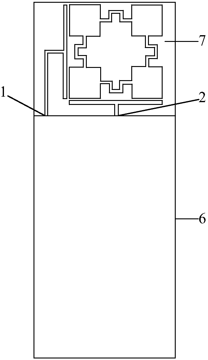
[0118] Embodiment 1: The size of the motherboard of the whole machine is 60×80mm, such as figure 2 shown. An antenna clearance area 7 of 60×18 mm is reserved on the top of the main board.

[0119] In this embodiment, the MIMO antenna consists of five parts:

[0120] 1) 4 patch antennas 41-44, the patch antennas are square;

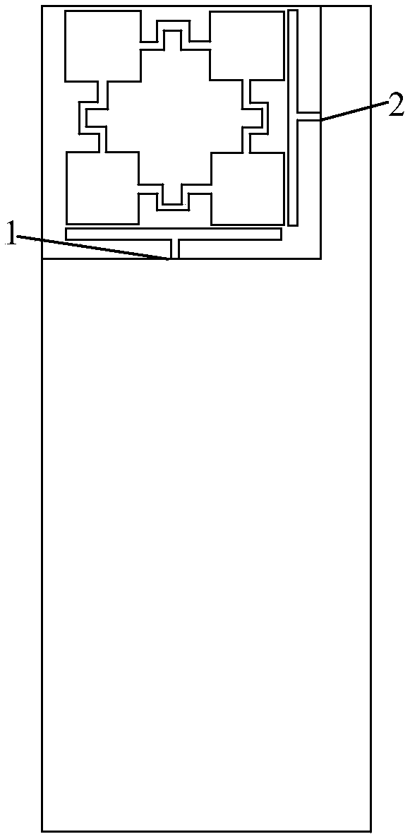
[0121] 2) Two T-shaped feed structures 31, 32, the T-shaped feed structure 31 is located on the left side of the antenna structure, and of course it can also be designed to be located on the right side of the antenna structure (such as image 3 shown).

[0122] 3) Bending the microstrip line 51-54;

[0123] 4) The dielectric board is located at the bottom;

[0124] 5) Copper-clad PCB board 6 .

[0125] The antenna structure of this embodiment mainly uses four square patch antennas 41-44, which form a square shape by bending microstrip lines 51-54. As shown in the figure, the patch antennas are connected by a microstrip line with a bent structure, s...

Embodiment 2

[0130] Embodiment 2: In this embodiment, the position of the MIMO antenna can be arranged in any direction on the main board of the terminal. The position of the MIMO antenna can be adjusted according to the layout requirements, for example, it can be the top, the side or the bottom area of ​​the main board. like image 3 As shown, the entire MIMO antenna layout is on the upper left corner of the motherboard, and the T-shaped feed structure of the diversity antenna is placed on the right.

Embodiment 3

[0131] Embodiment 3: In this embodiment, the number of square patch antennas can be flexibly adjusted. like Figure 5 As shown, a three-column and three-row structure (eight patch antennas are used), and each patch antenna is still connected by a bent microstrip line. The bending structure of the bent microstrip line is mainly to widen the low-frequency bandwidth of the antenna, and other bending styles can also be used.


PUM

PropertyMeasurementUnit
Thicknessaaaaaaaaaa

Abstract

The invention discloses a multi-input-multi-output (MIMO) antenna and a terminal. The MIMO antenna at least comprises a main antenna and a branch antenna, wherein the main antenna and the branch antenna are arranged on the same antenna structure, the main antenna is polarized along a first direction and is used for transmitting a signal of the main antenna, the branch antenna is polarized along asecond direction and is used for transmission a signal of the branch antenna, and the signal of the main antenna and the signal of the branch antenna are orthogonally polarized.

Description

technical field [0001] The present invention relates to Multiple-Input Multiple-Output (MIMO, Multiple-Input Multiple-Out-put) technology, in particular to a MIMO antenna and terminal. Background technique [0002] MIMO technology is a major breakthrough in antenna technology in the field of wireless mobile communications. MIMO technology can double the capacity and spectrum utilization of the communication system without increasing the bandwidth. It is a key technology that must be adopted in the new generation of mobile communication systems. MIMO technology allows multiple antennas to transmit and receive multiple spatial streams simultaneously, and can distinguish signals to or from different spatial orientations. The application of the multi-antenna system enables parallel data streams to be transmitted simultaneously. At the same time, using multiple antennas at the sending end or receiving end can significantly overcome channel fading and reduce the bit error rate. ...

Claims


Application Information

Patent Timeline
IPC IPC(8): H01Q1/22H01Q1/38H01Q1/50H01Q21/00H01Q21/24
CPCH01Q1/22H01Q1/38H01Q1/50H01Q1/52H01Q21/00H01Q21/24H01Q21/0006
Inventor 刘洋
Owner ZTE CORP
Why Eureka
Try Eureka