Rotor structure, permanent magnetism auxiliary synchronization magnetic resistance motor and electric vehicle

A technology of rotor structure and permanent magnet slots, which is applied in the direction of electric vehicles, motors, electric components, etc., can solve the problem of low anti-demagnetization ability of motors, achieve the goal of enhancing anti-demagnetization ability, improving the utilization rate of magnetic field, and increasing torque output Effect

Active Publication Date: 2018-07-24
ZHUHAI GREE REFRIGERATION TECH CENT OF ENERGY SAVING & ENVIRONMENTAL PROTECTION
View PDF5 Cites 9 Cited by
  • Summary
  • Abstract
  • Description
  • Claims
  • Application Information

AI Technical Summary

Problems solved by technology

[0003] The main purpose of the present invention is to provide a rotor structure, a permanent magnet assisted synchronous reluctance motor and an electric vehicle to solve the problem of low anti-demagnetization ability of the motor in the prior art

Method used


Image

  • Rotor structure, permanent magnetism auxiliary synchronization magnetic resistance motor and electric vehicle
  • Rotor structure, permanent magnetism auxiliary synchronization magnetic resistance motor and electric vehicle
  • Rotor structure, permanent magnetism auxiliary synchronization magnetic resistance motor and electric vehicle

Examples


Embodiment Construction

[0061] It should be noted that, in the case of no conflict, the embodiments in the present application and the features in the embodiments can be combined with each other. The present invention will be described in detail below with reference to the accompanying drawings and examples.

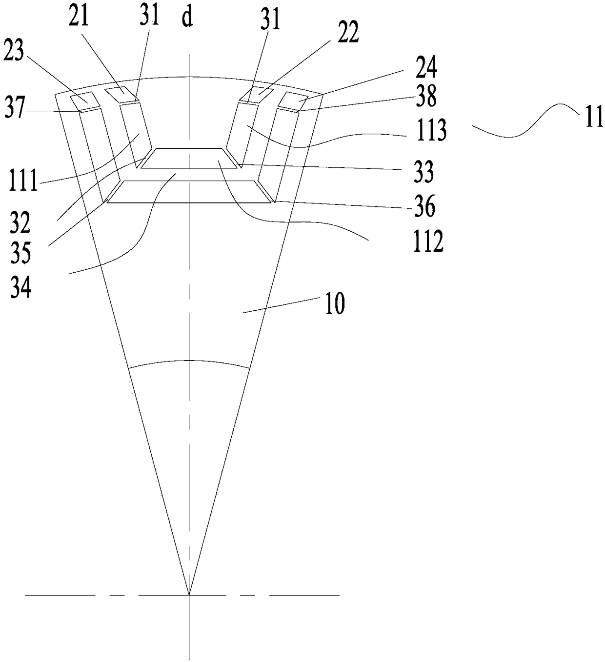
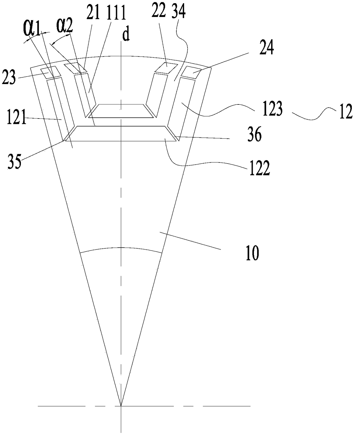
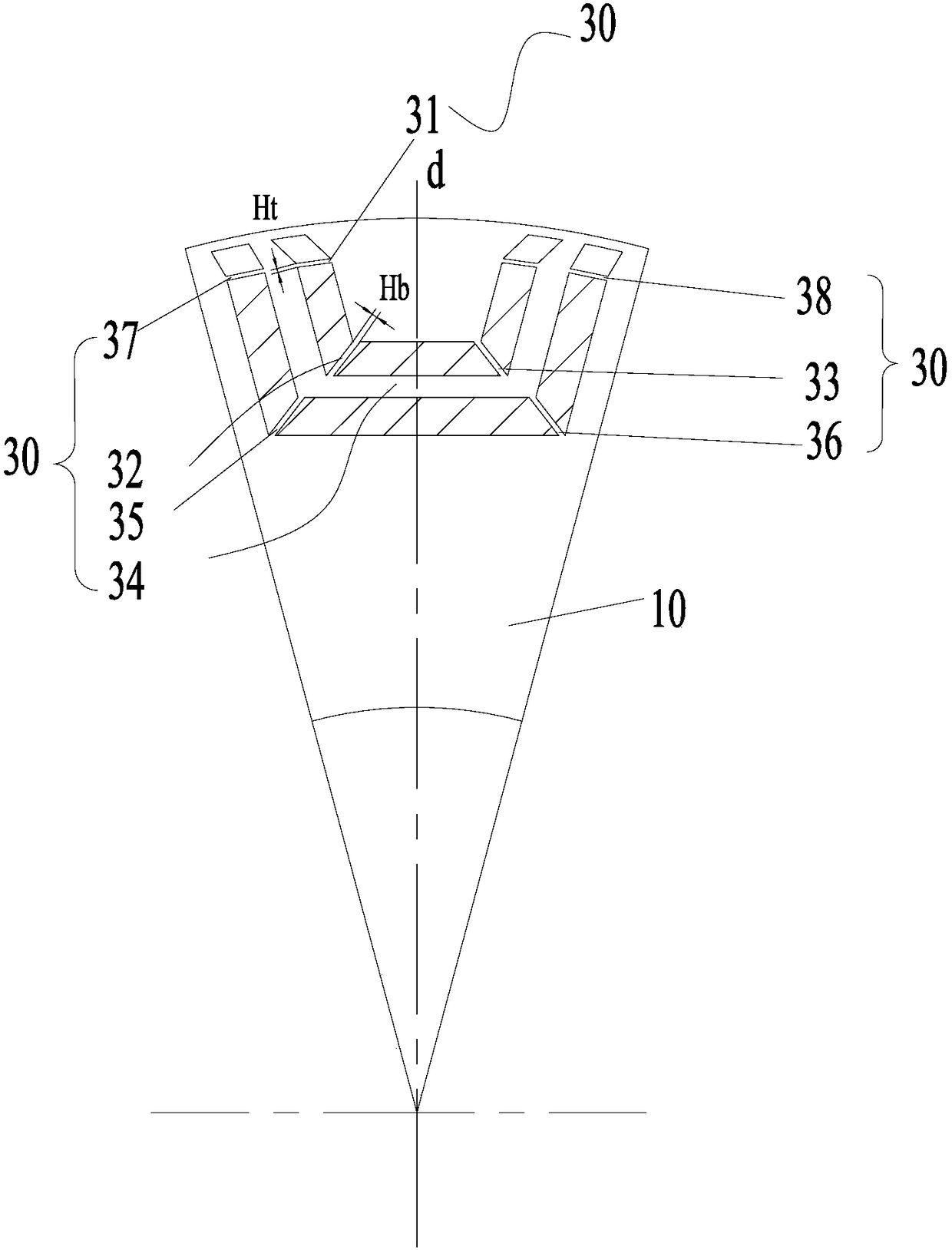
[0062] combine Figure 1 to Figure 17 As shown, according to an embodiment of the present invention, a rotor structure is provided.

[0063] Specifically, the rotor includes a rotor body 10, and the rotor body 10 is provided with a permanent magnet slot group, the permanent magnet slot group includes an outer permanent magnet slot 11, and the rotor body 10 is also provided with a first air slot 21, the first air slot The first end of 21 communicates with or is adjacent to the end of the outer permanent magnet slot 11, and the second end of the first air slot 21 extends toward the outer edge of the rotor body 10 and is gradually set away from the direct axis of the rotor body 10. When the firs...


PUM


Abstract

The invention provides a rotor structure, a permanent magnetism auxiliary synchronization magnetic resistance motor and an electric vehicle; the rotor structure comprises a rotor body having a permanent magnet slot set; the permanent magnet slot set comprises an outer permanent magnet slot; the rotor body is also provided with a first air slot; a first end of the first air slot and the end portionof the outer permanent magnet slot are connected or adjacent to each other; a second end of the first air slot extends to the outer edge of the rotor body and gradually gets away from the straight axle of the rotor body; when the first end of the first air slot is adjacent to the end portion of the outer permanent magnet slot, a first magnetic conductive channel is formed between the first end ofthe first air slot and the end portion of the outer permanent magnet slot. The rotor body is provided with the air slot that decides the direction of a rotor magnetic path, thus reducing magnetic flux leakage in a process in which the stator magnetic field reaches the rotor via an air gap, improving the magnetic field utilization rate, increasing torque output, minimizing demagnetization effect on the permanent magnet by a demagnetization magnetic field, and enhancing the anti-demagnetization capability.

Description

technical field [0001] The invention relates to the technical field of motor equipment, in particular to a rotor structure, a permanent magnet assisted synchronous reluctance motor and an electric vehicle. Background technique [0002] Permanent magnet motors have the advantages of high efficiency and good mechanical properties, and are widely used in various fields of modern industry, but permanent magnets have inevitable demagnetization. Once demagnetized, it will lead to a decrease in the performance of the motor such as torque and efficiency. In severe cases, the motor may lose control and cause accidents. With the development of the times, permanent magnet motors tend to be miniaturized. Furthermore, the motors in the prior art still have the problem of low demagnetization resistance. Contents of the invention [0003] The main purpose of the present invention is to provide a rotor structure, a permanent magnet assisted synchronous reluctance motor and an electric v...

Claims


Application Information

Patent Timeline
Patent Type & Authority Applications(China)
IPC IPC(8): H02K1/27H02K29/03
CPCH02K1/2766H02K29/03H02K2213/03H02K1/2773Y02T10/64
Inventor 陈彬胡余生肖勇童童卢素华
Owner ZHUHAI GREE REFRIGERATION TECH CENT OF ENERGY SAVING & ENVIRONMENTAL PROTECTION
Why Eureka
Try Eureka