Optical receiver, active optical cable, and control method for optical receiver

A technology of optical receiver and control method, which is applied in the direction of electromagnetic receiver, light-controlled amplifier, photometric method, etc., and can solve the problems of output signal waveform distortion of optical receiver 2, etc.

Inactive Publication Date: 2018-07-24
FUJIKURA LTD
View PDF6 Cites 3 Cited by
  • Summary
  • Abstract
  • Description
  • Claims
  • Application Information

AI Technical Summary

Problems solved by technology

Therefore, the waveform of the output signal of the optical receiver 2 is distorted from the time when the transition from the IDLE period to the DATA period to the time when the output voltage Vth of the error amplifier 22g catches up with the average output level of the transimpedance amplifier 22a in the DATA period.

Method used


Image

  • Optical receiver, active optical cable, and control method for optical receiver
  • Optical receiver, active optical cable, and control method for optical receiver
  • Optical receiver, active optical cable, and control method for optical receiver

Examples


Embodiment Construction

[0032] [Structure of Optical Receiver]

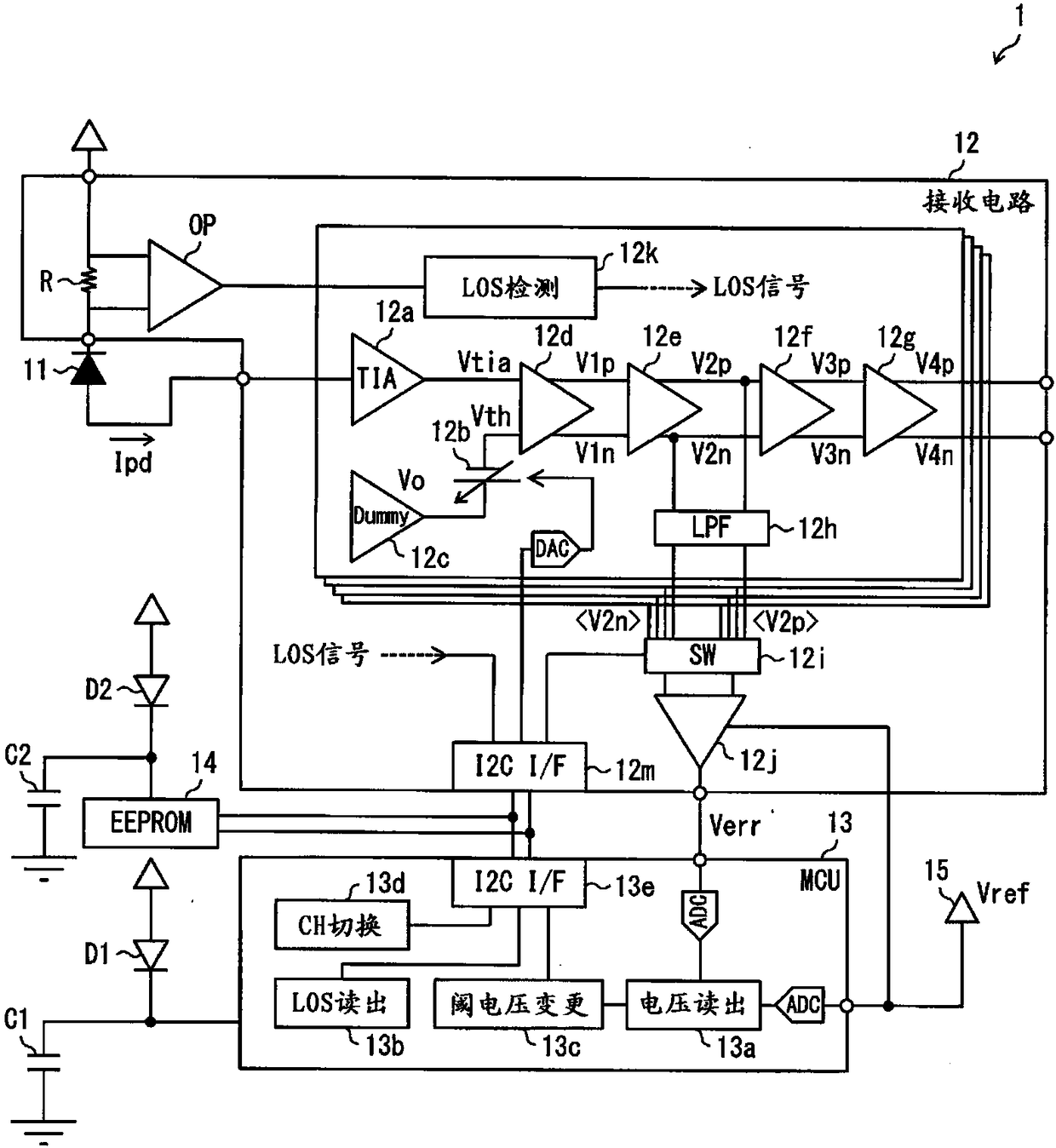
[0033] refer to figure 1 The configuration of the optical receiver 1 will be described. figure 1 is a block diagram showing the configuration of the optical receiver 1 .

[0034]The optical receiver 1 is a device that converts a received optical signal into a voltage signal (differential voltage signal in this embodiment) and outputs it to the outside. Such as figure 1 As shown, the optical receiver 1 includes a light receiving element 11 , a receiving circuit 12 , an MCU (MicroController Unit: Micro Control Unit) 13 , a nonvolatile memory 14 , and a reference voltage source 15 .

[0035] The light receiving element 11 is configured to convert a received light signal into a current signal. In this embodiment, a PD (Photo Diode: Photodiode) is used as the light receiving element 11 . The current signal obtained by the light receiving element 11 is input to the receiving circuit 12 .

[0036] The receiving circuit 12 is configure...


PUM


Abstract

The invention provides an optical receiver. The optical receiver is provided with: a light receiving element (11) for converting an optical signal into a current signal; a transimpedance amplifier (12a) for converting the current signal into a voltage signal; a differential amplifier (12d) for converting the voltage signal into a differential signal by differentially amplifying a difference between the voltage signal and a threshold voltage; an LOS detection circuit (12k) for detecting a no-signal section of the optical signal; and an MCU (13) for repeating offset cancel processing including threshold voltage change processing for changing the threshold voltage such that the offset voltage of the differential signal decreases, wherein the MCU (13) skips the threshold voltage change processing in the no-signal section.

Description

[0001] This application is a divisional application of the invention patent application with the application number 201580055667.4, the application date is April 13, 2017, and the invention title is "Optical Receiver, Active Optical Cable, and Control Method for Optical Receiver". technical field [0002] The present invention relates to an optical receiver that converts a received optical signal into a voltage signal and outputs it to the outside. In addition, the present invention relates to an active optical cable including such an optical receiver. Furthermore, the present invention relates to a method of controlling such an optical receiver. Background technique [0003] Active optical cables are attracting attention as transmission media that replace metal cables. The active optical cable is composed of a cable for accommodating optical fibers and a pair of connectors provided at both ends of the cable. One connector functions as an optical transmitter that converts ...

Claims


Application Information

Patent Timeline
Patent Type & Authority Applications(China)
IPC IPC(8): H04B10/69H03F3/08H03F3/45
CPCH03F3/087H03F3/45475H03F3/45968H03F2200/405H03F2203/45212H03F2200/375H03F2200/453H03F2200/462H03F2200/481H03F2203/45152H04B10/695G01J1/44H04B10/69G01J2001/444H04B10/697
Inventor 田中贵之林美奈子
Owner FUJIKURA LTD
Why Eureka
Try Eureka