
Water-cooling backboard heat dissipating device and control method thereof

A technology of heat dissipation device and air cooling device, which is applied in cooling/ventilation/heating transformation, electrical components, electrical equipment structural parts, etc. and other problems, to achieve the effect of simple structure, improved cooling efficiency and high heat dissipation efficiency

Pending Publication Date: 2018-07-24
GUANGDONG SHENLING ENVIRONMENT SYST CO LTD
View PDF7 Cites 2 Cited by
  • Summary
  • Abstract
  • Description
  • Claims
  • Application Information

AI Technical Summary

Problems solved by technology

As the name implies, the water-cooled backplane is a heat dissipation method that circulates water through the water-cooling pipes behind the backplane to take away the heat of the cabinet. In principle, the larger the water volume, the faster the water goes, and the more heat is taken away at the same time. , the better the heat dissipation effect, but too much water and too fast water flow often require the circulation system to provide greater kinetic energy, and sometimes the heat dissipation of the cabinet is not large, resulting in relatively low energy efficiency
Recently, new types of water-cooled backplanes have also begun to appear in China, such as the Chinese utility model patents with application numbers 201420715402.5 and 201420691326.9, which improve the energy efficiency of the water-cooled backplane by improving the heat exchange pipe design of the water-cooled backplane, but only improve the water-cooled backplane. The heat exchange pipe of the plate can only solve the problem to a certain extent, and the effect of improving energy efficiency is average, and it cannot realize the intelligent control of the water-cooled back plate, and the flexibility is poor

Method used


Image

  • Water-cooling backboard heat dissipating device and control method thereof

Examples


Embodiment

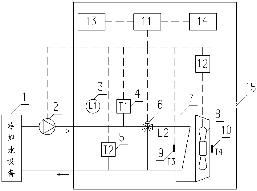
[0031] A water-cooled backplane cooling device, such as figure 1 As shown, it includes a cooling water unit 1, a water pump 2, a water-cooled backplane 15 and a control device; the cooling water unit 1, the water pump 2 and the water-cooled backplane 15 form a circulation loop through pipelines; the water-cooled backplane 15 includes a heat exchanger 7 and a The air cooling device 8 on one side of the heat exchanger 7, the cooling water of the cooling water unit 1 is passed into the heat exchanger 7 by the heat exchanger water inlet pipe for heat exchange, and then returned to the cooling water unit 1 by the heat exchanger outlet pipe, and exchanged A bypass pipe is also provided between the water inlet pipe of the heat exchanger and the water outlet pipe of the heat exchanger, and a flow regulating device 6 is arranged between the water inlet pipe of the heat exchanger and the bypass pipe. The control device is used to realize the intelligent control of the water pump 2 , the...


PUM


Abstract

The invention discloses a water-cooling backboard heat dissipating device which comprises a water-cooling backboard. A circulation loop is formed by a cooling water unit, a water pump and the water-cooling backboard through a pipeline. The water-cooling backboard comprises a heat exchanger and an air-cooling device on one side of the heat exchanger. After cooling water of the cooling water unit istransferred from a heat exchanger water inlet pipe to the heat exchanger for heat exchange, and the cooling water returns to the cooling water unit by a heat exchanger water outlet pipe. A bypass pipe is arranged between the heat exchanger water inlet pipe and the heat exchanger water outlet pipe, and a flow regulating device is arranged between the heat exchanger water inlet pipe and the bypasspipe. The invention also a control method of the above water-cooling backboard heat dissipating device. Compared with the prior art, the hot air blown by a server is directly recirculated and used after being cooled by the backboard, under the intelligent control of a PLC, the accurate cooling for a hot object can be realized, the efficiency is high, and the energy consumption is low. The specialdesign of an air duct is not needed, air flows directly from the back of the server to the front side, the airflow organization is simple and reasonable, the design and installation are simple, and the energy saving effect of airflow transportation is more remarkable.

Description

technical field [0001] The invention relates to the field of data center cooling, in particular to a water-cooled backplane heat dissipation device and a control method thereof. Background technique [0002] With the continuous development of information technology, the number of computer servers is increasing day by day. As we all know, due to the large amount of information processing and long-term operation of servers, the heat generation is huge, and there are operating characteristics of high calorific value and local overheating. [0003] The traditional computer room air conditioner cools the overall environment, but the mixing of hot and cold airflow causes thermal loss and the cooling efficiency is low. In the case of local overheating of the cabinet, the local hot spot can only be eliminated by further reducing the temperature of the entire computer room, which further increases the energy consumption of the cabinet cooling and further reduces the cooling efficienc...

Claims


Application Information

Patent Timeline
Patent Type & Authority Applications(China)
IPC IPC(8): H05K7/20
CPCH05K7/20736H05K7/20781H05K7/20836
Inventor 韦成栋陈志宏周圆圆
Owner GUANGDONG SHENLING ENVIRONMENT SYST CO LTD
Learn More