Multifunctional pneumatic microfluid control system, intermittent sample injection system and control method

A control system and microfluidic technology, applied in the field of microfluidics, can solve the problems of complicated operation, continuous sampling time limitation, etc., and achieve the effect of preventing cross-contamination

Inactive Publication Date: 2018-07-27
ENERGY RES INST OF SHANDONG ACAD OF SCI
View PDF0 Cites 4 Cited by
  • Summary
  • Abstract
  • Description
  • Claims
  • Application Information

AI Technical Summary

Problems solved by technology

At present, the most widely used method in microfluidic experiments is to use the plunger pump to push the fluid into the chip. The disadvantage of this method is that the continuous injection time is limited by the volume of the syringe pump and the operation is relatively complicated.

Method used


Image

  • Multifunctional pneumatic microfluid control system, intermittent sample injection system and control method
  • Multifunctional pneumatic microfluid control system, intermittent sample injection system and control method
  • Multifunctional pneumatic microfluid control system, intermittent sample injection system and control method

Examples


Embodiment 1

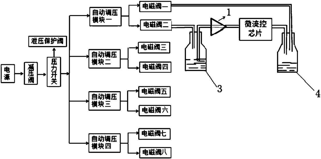
[0071] The first control method is as figure 2 As shown, the pneumatic microfluidic control system capable of intermittent sample injection adopts the described multifunctional pneumatic microfluidic control system, the microfluidic chip is connected to the air inlet of the second liquid container 4 through a pipeline, and the second liquid The liquid outlet pipe of the container is connected to another solenoid valve on the branch connected with the outlet pipe of the corresponding automatic pressure regulating module.

[0072] The control method of the control system includes:

[0073] The parameters set through the control panel include the opening of each automatic pressure regulation module, the stop of each automatic pressure regulation module, the pressure value of each automatic pressure regulation module, the opening of each solenoid valve, the stop of each solenoid valve and the setting of each solenoid valve. start time and stop time;

[0074] Regulate the pressu...

Embodiment 2

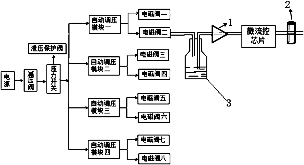
[0082] The second control method is as image 3 As shown, the pneumatic microfluidic control system capable of intermittent sampling adopts the multifunctional pneumatic microfluidic control system described above, and a pinch valve 2 is provided on the output pipeline of the microfluidic chip.

[0083] The control method of the control system includes:

[0084] The parameters set through the control panel include the opening of each automatic pressure regulation module, the stop of each automatic pressure regulation module, the pressure value of each automatic pressure regulation module, the opening of each solenoid valve, the stop of each solenoid valve and the setting of each solenoid valve. start time and stop time;

[0085] Regulate the pressure of the whole system through the pressure reducing valve;

[0086] The pressure value of the control system is displayed through the pressure switch, and the upper and lower limits of pressure can be set through the pressure swit...


PUM


Abstract

The invention discloses a multifunctional pneumatic microfluid control system, an intermittent sample injection system and a control method. The multifunctional pneumatic microfluid control system comprises an air source. A pressure relief valve and a pressure switch are arranged on an air outlet pipeline of the air source. The pipeline behind the pressure switch is divided into a plurality of branches. An automatic pressure adjusting module is arranged on each branch. An outlet pipeline of each automatic pressure adjusting module is connected with at least two branches. An electromagnetic valve is arranged on each branch. The electromagnetic valve on one of the branches connected with the outlet pipeline of each automatic pressure adjusting module is connected with an air inlet of a firstliquid container through a pipeline. A liquid outlet pipeline of the first liquid container is connected with a micro-fluidic chip through a check valve. The automatic pressure adjusting modules andthe electromagnetic valves are connected with a control panel. Instantaneous stop of microfluids can be realized simply, conveniently and rapidly through the check valve, and cross contamination of fluids can be avoided effectively. By the multifunctional pneumatic microfluid control system, both continuous sample injection and intermittent sample injection can be realized.

Description

technical field [0001] The invention relates to the field of microfluidic technology, in particular to a multifunctional pneumatic microfluidic control system, an intermittent sampling system and a control method. Background technique [0002] Microfluidic technology refers to the science and technology involved in the use of micron-scale pipelines to process or manipulate tiny fluids (volumes ranging from nanoliters to attoliters), and is a discipline involving chemistry, fluid physics, microelectronics, new materials, biological Emerging interdisciplinary science and biomedical engineering. Because of the characteristics of miniaturization, integration, and intelligence, microfluidic devices are often called microfluidic chips, also known as lab-on-a-chip and micro-total analysis systems. [0003] The microfluidic analysis chip is a new generation of bedside diagnosis mainstream technology, which can provide fast and effective biochemical indicators directly around the su...

Claims


Application Information

Patent Timeline
Patent Type & Authority Applications(China)
IPC IPC(8): B01L3/00
CPCB01L3/50273B01L2200/028B01L2200/0642B01L2300/14B01L2400/0487B01L2400/0605
Inventor 侯延进田寒梅王雪莹李艳王建春滕竟争王立秋王建梅许敏
Owner ENERGY RES INST OF SHANDONG ACAD OF SCI
Why Eureka
Try Eureka