Adjustable single-drive tapered tooth cutting device

A cutting equipment, single-drive technology, applied in mechanical equipment, metal processing equipment, gear teeth, etc., can solve the problems of vulnerability, heavy cutting equipment load, affecting the quality of workpieces, etc., to reduce the cost of use, ensure processing quality, improve The effect of generality

Inactive Publication Date: 2018-07-27
CHANGZHOU COLLEGE OF INFORMATION TECH
View PDF0 Cites 0 Cited by
  • Summary
  • Abstract
  • Description
  • Claims
  • Application Information

AI Technical Summary

Problems solved by technology

There are two defects in this cutting method. One is that the shape of the cutter is fixed. If you want to adjust the length and angle of the cutting sawtooth, you need to replace the cutter, and the cutter needs to be molded separately, and because of the sharpness problem, It is a fragile consumable and needs to be replaced. For a long bevel tooth workpiece, if the one-time cutting method is used, the load on the cutting equipment will be greater, and the pressure on the cutter body will be greater, which may easily cause the knife to curl or break. If multiple cuts are used, since the workpiece is placed horizontally, if the workpiece moves during cutting or lifting the knife, the processing quality will be affected; second, after horizontal cutting, the receiving knife surface will be slightly concave, while the back knife surface will be slightly convex Starting, that is, the deformation along the cutting direction, the deformation will have different degrees of inclination according to different materials, and for some workpieces, it will seriously affect the quality of the workpiece
In addition, the cutting, transmission and other operations of the existing cutting equipment are realized by multiple sets of drives, the electric control is inconvenient, and the maintenance cost is high

Method used


Image

  • Adjustable single-drive tapered tooth cutting device
  • Adjustable single-drive tapered tooth cutting device

Examples


Embodiment 1

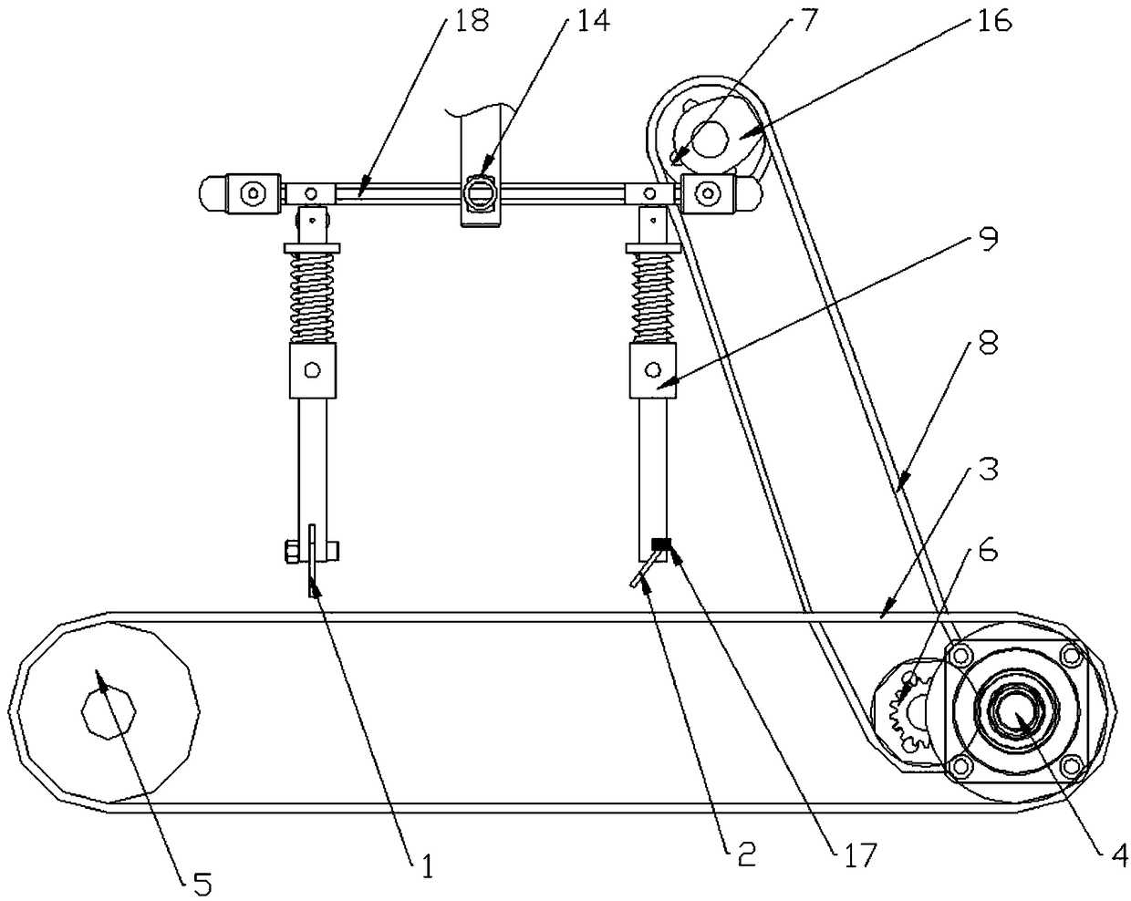
[0027] Equipment working mechanism:

[0028] The drive motor 4 is started, driven by the transmission gear 6 to drive the pulley 5, and the pulley drives the conveyor belt 3 to rotate to transport the workpiece.

[0029] The driving transmission wheel on the left side of the transmission gear 6 realizes the driving of the driven transmission wheel 7 through the transmission belt 8, so that the final shaft 16 rotates,

[0030] The pressing shaft 16 is an elliptical pressing roller. During the rotation of the pressing shaft 16, since it is in contact with the top surface of the transmission connecting rod 18, when the long diameter of the ellipse is in contact with the transmission connecting rod 18, will push it down,

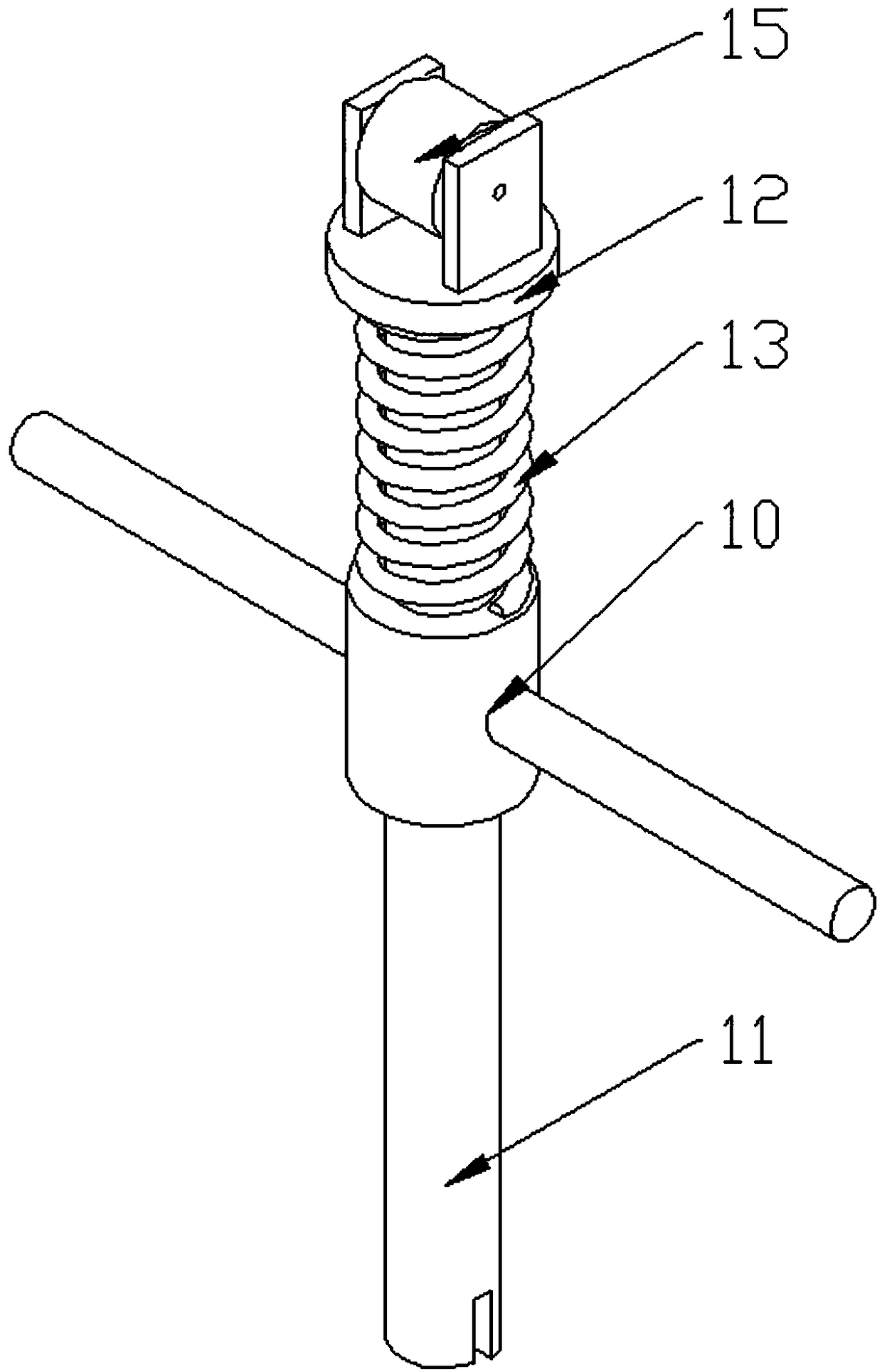
[0031] During the pressing down process, the pressure roller 15 will roll along the bottom surface of the transmission connecting rod 18, and drive the guide rod 11 to move downward, and move downward together with the oblique cutter 2 to realize the oblique cu...

Embodiment 2

[0035] For the adjustment of cutting parameters:

[0036] During the cutting process, it is necessary to adjust the cutting slope, cutting distance, cutting depth, and the length of the top surface of each bevel tooth. This adjustment is realized by adjusting different components in the equipment.

[0037] Although the adjustment of the wheel diameter of the pulley 5 can realize the adjustment of the conveying speed of the conveyor belt when other variables are constant, in order to ensure the complete installation of the equipment and the convenient adjustment, such major changes as the replacement of the pulley 5 are not carried out. adjust.

[0038] Adjusting the depth at which the vertical cutter 1 is embedded in the guide rod 11 can adjust the cutting depth of the vertical cutter 1,

[0039] Adjusting the height at which the guide rod 11 is embedded in the notch can realize the adjustment of the cutting depth of the oblique cutter 2,

[0040] By adjusting the angle of i...

Embodiment 3

[0044] Installation of auxiliary equipment:

[0045] The operation mechanism described in embodiment 1 is the basic operation mechanism, if more functional improvements are needed, the equipment can be refitted,

[0046] A clutch assembly is installed between the transmission drying 18 and the final shaft 16, which can realize the separation of the conveyor belt 3 transportation and cutting, thereby ensuring the control of workpiece movement and loading during cutting, and improving the cutting effect.

[0047] The transmission of the transmission belt 7 can be cancelled, and the workpiece transportation and cutting can be respectively realized by two motors. At this time, the cutting parameters can also be adjusted by the motor speed, which simplifies the adjustment steps.


PUM


Abstract

An adjustable single-drive tapered tooth cutting device comprises a perpendicular cutter, an inclined cutter and a conveyer belt. The perpendicular cutter, the inclined cutter and the conveyer belt are driven by a drive motor. The drive motor and a belt pulley of the conveyer belt are in transmission connection in a meshed manner through a transmission gear. The perpendicular cutter and the inclined cutter are both installed on linkage assemblies. The linkage assemblies of the perpendicular cutter and the inclined cutter are connected through a transmission connection rod. The transmission connection rod is driven through transmission wheels. The transmission wheels and the belt pulleys are in transmission through a transmission belt. The transmission wheels comprise a driving transmissionwheel and a driven transmission wheel. The adjustable single-drive tapered tooth cutting device has the beneficial effects that tapered tooth cutting in the perpendicular direction of a workpiece canbe achieved, lateral deformation is avoided, the machining quality of the workpiece is guaranteed, the cutting length, the cutting depth and the cutting interval can be adjusted, the use cost of thedevice is reduced, and the universality of the adjustable single-drive tapered tooth cutting device is improved.

Description

technical field [0001] The invention relates to the field of machining tooling, in particular to a cutting tool for tapered sawtooth cutting. Background technique [0002] The existing cutting principle of the bevel tooth structure for the workpiece is to place the workpiece horizontally, and then realize the cutting by the cutter with the bevel tooth structure. There are two defects in this cutting method. One is that the shape of the cutter is fixed. If you want to adjust the length and angle of the cutting sawtooth, you need to replace the cutter, and the cutter needs to be molded separately, and because of the sharpness problem, It is a fragile consumable and needs to be replaced. For a long bevel tooth workpiece, if the one-time cutting method is used, the load on the cutting equipment will be greater, and the pressure on the cutter body will be greater, which may easily cause the knife to curl or break. If multiple cuts are used, since the workpiece is placed horizont...

Claims


Application Information

Patent Timeline
Patent Type & Authority Applications(China)
IPC IPC(8): B23F9/00B23F21/00
CPCB23F9/00B23F21/00
Inventor 汪涵蒋继平
Owner CHANGZHOU COLLEGE OF INFORMATION TECH
Why Eureka
Try Eureka