Automatic feeding type grinding wheel cutting machine
What is Al technical title?
Al technical title is built by PatSnap Al team. It summarizes the technical point description of the patent document.
A grinding wheel cutting machine and automatic feeding technology, which is applied to the grinding frame, grinding drive device, grinding machine parts and other directions, can solve the problems of laborious operation of operators, uneven cutting surface, low work efficiency, etc. To achieve the effect of good cutting effect, high safety performance and simple structure
Pending Publication Date: 2018-07-27
QINZHOU UNIV
View PDF0 Cites 3 Cited by
Summary
Abstract
Description
Claims
Application Information
AI Technical Summary
This helps you quickly interpret patents by identifying the three key elements:
Problems solved by technology
Method used
Benefits of technology
Problems solved by technology
When cutting metal materials, the grinding wheel cutting machine is directly placed on the level ground for use. When cutting the opposite pipe, round pipe, special-shaped pipe, steel bar, etc., the operator manually lifts up or presses down the operating rod at the right end of the cutting motor. Thereby controlling the upward or downward movement of the grinding wheel cutting piece when cutting metal materials, due to the need to use manpower to operate the operating lever, the operation time will cause the operator to work hard and the work efficiency is low; and when manually operating the operating lever, the operator needs to Standing at the rear end of the rotating grinding wheel cutting disc, when the grinding wheel cutting disc is damaged, the grinding wheel cutting fragments are thrown backward, or the cut metal material is thrown backward due to improper operation, it is easy to cause personal injury accidents, and the safety performance is low; In addition, there are many uncertain factors in manual cutting, such as manpower, speed control, etc., resulting in uneven cutting surface and poor cutting effect
Method used
Image
Click on the blue label to locate the original text in one second.
Reading with bidirectional positioning of images and text.
Examples
Embodiment Construction
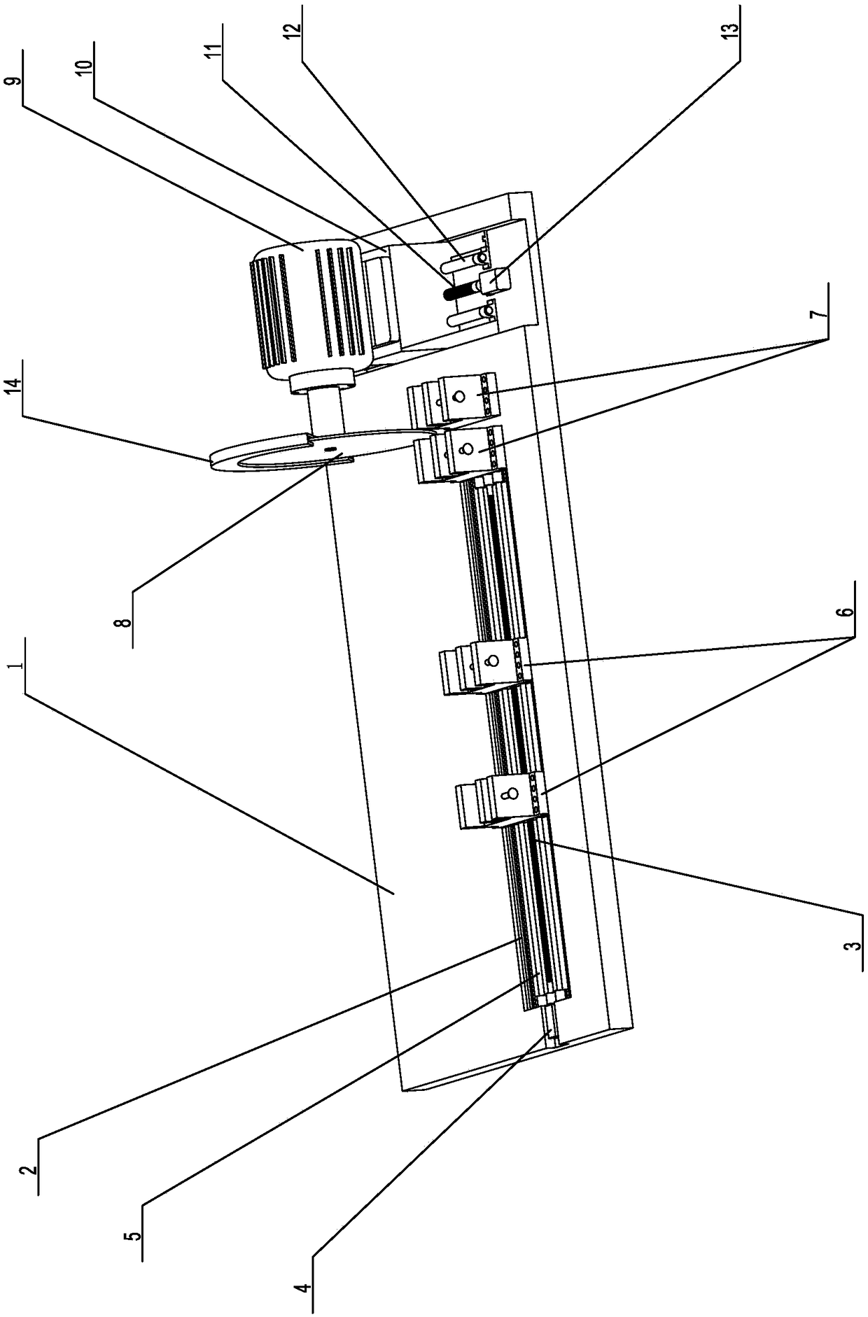
[0016] Such as figure 1 Propose a kind of specific embodiment of the present invention as shown, automatic feeding type grinding wheel cutting machine, comprise the bottom plate 1 that is rectangular shape, described bottom plate 1 surface offers a groove 2 along its lengthwise direction, in described groove 2, set There is an X-axis ball screw 3, the end of the X-axis ball screw 3 is connected to an X-axis motor 4, and the groove 2 is also provided with X-axis guide rails 5 located on both sides of the X-axis ball screw 3, The X-axis ball screw 3 and the two X-axis guide rails 5 successively run through several movable fixtures 6, and the movable fixture 6 moves linearly along the two X-axis guide rails 5 driven by the X-axis ball screw 3, and moves adjacently The distance between the clamps 6 is equal, two fixed clamps 7 are provided on the bottom plate 1 and at the end of the groove 2, the two fixed clamps 7 and the movable clamps 6 are all located on the same straight line...
PUM
Abstract
The invention provides an automatic feeding type grinding wheel cutting machine. The automatic feeding type grinding wheel cutting machine comprises a bottom plate which is provided with an X axis ball screw, an X axis motor, two X axis guide rails, a movable clamp and two fixed clamps; a grinding wheel fixed to a grinding wheel driver is arranged between the two fixed clamps, and the grinding wheel driver is arranged on a driver supporting base; and the driver supporting base achieves movement on the Y axis through a Y axis ball screw and two Y axis guide rails. According to the grinding wheel cutting machine, a motor is adopted to drive the ball screws to achieve linear movement of a cut piece and the grinding wheel, full-automatic mechanical cutting is achieved, and the defects of existing manual operation are overcome; on one hand, the labor amount of manpower is greatly reduced, and the work efficiency is improved, and on the other hand, the safety performance is high, and the safety of an operator is guaranteed; besides, movement of the cut piece and the grinding wheel is accurate, cutting is flat, the cutting effect is good; and the grinding wheel cutting machine is simple in structure and can be easily manufactured.
Description
technical field [0001] The invention relates to a cutting device, in particular to an automatic feeding grinding wheel cutting machine. Background technique [0002] Grinding wheel cutting machine, also called grinding wheel saw, is a commonly used cutting machine, mainly used to cut square tubes, round tubes, special-shaped tubes, steel bars, etc. with small diameters. The grinding wheel cutting machine is light, flexible, simple and convenient to use, and is widely used in construction, hardware, petrochemical, mechanical metallurgy, hydropower installation and other fields, especially in construction, the cutting processing of steel bars is relatively high. [0003] The grinding wheel cutting machine is generally composed of a base, a grinding wheel, a motor or other power sources, a bracket, a protective cover and a water feeder, etc., and the grinding wheel is arranged on the top surface of the base. When cutting metal materials, the grinding wheel cutting machine is d...
Claims
Application Information
Patent Timeline
Application Date:The date an application was filed.
Publication Date:The date a patent or application was officially published.
First Publication Date:The earliest publication date of a patent with the same application number.
Issue Date:Publication date of the patent grant document.
PCT Entry Date:The Entry date of PCT National Phase.
Estimated Expiry Date:The statutory expiry date of a patent right according to the Patent Law, and it is the longest term of protection that the patent right can achieve without the termination of the patent right due to other reasons(Term extension factor has been taken into account ).
Invalid Date:Actual expiry date is based on effective date or publication date of legal transaction data of invalid patent.