Dustproof solar recharge pole for new energy automobile

A technology for new energy vehicles and charging piles, applied in electric vehicle charging technology, charging stations, electric vehicles, etc., can solve problems affecting the charging performance of charging piles, dust accumulation in charging piles, and weakened dustproof effect, etc., and achieve good sealing , improved dust resistance, good sealing effect

Inactive Publication Date: 2018-07-27
DONGGUAN UNIV OF TECH +1
View PDF0 Cites 3 Cited by
  • Summary
  • Abstract
  • Description
  • Claims
  • Application Information

AI Technical Summary

Problems solved by technology

[0003] At present, charging piles are generally installed in public buildings (public buildings, shopping malls, public parking lots, etc.) and residential parking lots or charging stations, and provide charging services for electric vehicles through convenient functions. However, most of the existing charging piles are high-power charging equipment , it will generate heat and need to be dissipated, and the charging pile is placed outdoors, and the dust from the outside will enter the charging pile from the heat dissipation place, causing the accumulation of dust inside the charging pile and affecting the charging performance of the charging pile; and the back cover of the charging pile is due to frequent maintenance. It needs to be disassembled, which will affect its sealing, and its dustproof effect will be weakened. The charging pile needs additional power to charge, resulting in a waste of energy

Method used


Image

  • Dustproof solar recharge pole for new energy automobile
  • Dustproof solar recharge pole for new energy automobile
  • Dustproof solar recharge pole for new energy automobile

Examples


Embodiment Construction

[0027] Below in conjunction with accompanying drawing and specific embodiment the present invention is described in further detail:

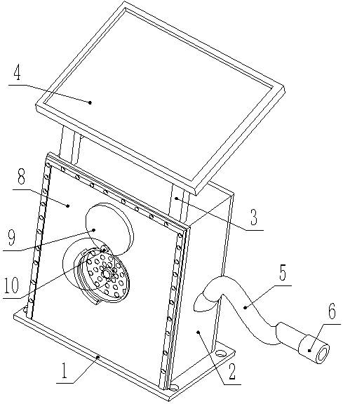
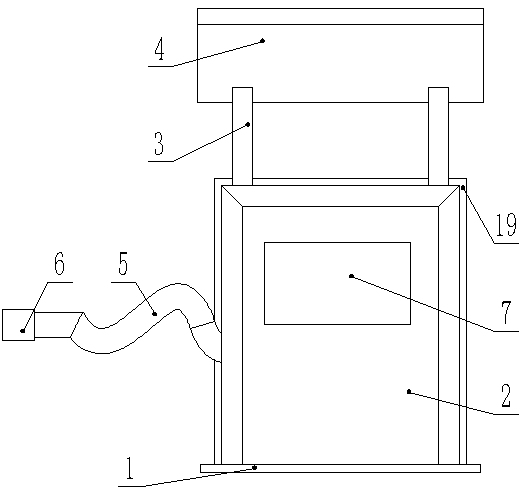
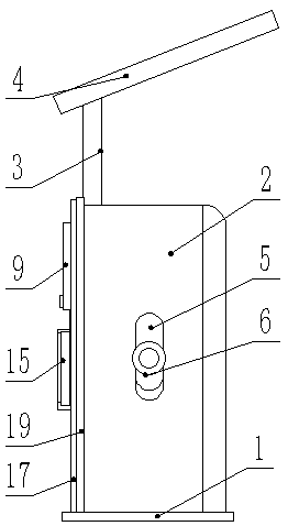
[0028] Such as Figure 1-Figure 7 As shown, a dust-proof solar charging pile for new energy vehicles includes a base 1, a charging pile housing 2 is fixed on the upper part of the base 1, and a central control panel 7 is provided at the front end of the charging pile housing 2. The top of the charging pile housing 2 is fixed with a support rod 3, and the upper part of the support rod 3 is fixed with a solar panel 4. The inside of the charging pile housing 2 is provided with a storage battery, which is electrically connected to the solar panel 4. A charging cable 5 is fixed on one side of the charging pile housing 2 , one end of the charging cable 5 is electrically connected to a charging plug 6 , and the charging cable 5 is electrically connected to a battery.

[0029] The rear end of the charging pile housing 2 is provided with a rear sealing ...


PUM

PropertyMeasurementUnit
Thicknessaaaaaaaaaa

Abstract

The invention discloses a dustproof solar recharge pole for a new energy automobile. The dustproof solar recharge pole comprises a base, wherein a recharge pole shell is fixed at the upper part of thebase; a central control screen is arranged at the front end of the recharge pole shell; a support rod is fixed at the top of the recharge pole shell; and a solar panel is fixed at the upper part of the support rod. According to the dustproof solar recharge pole, an electromagnet is controlled through a switch button, then the position of a dustproof cover can be changed, then the purposes that aheat radiation groove and all heat radiation holes can be covered by the dustproof cover and external dust can be prevented from entering the recharge pole when the device is not used can be achieved,the problem that dust enters into the recharge pole from the heat radiation holes and is accumulated can be solved, people do not need to disassemble a rear sealing plate to clean off the dust frequently, and service of the recharge pole can be ensured; and due to adoption of a W-shaped multi-stage sealing pad between the rear end of the recharge pole shell and the rear sealing plate, the rear sealing plate can be protected in a frame groove in the center of the multi-stage sealing pad, and the situation that dust penetrates through a sealing part of the rear sealing plate and enters the recharge pole to cause dust accumulation and the service of the recharge pole can be thus affected, can be avoided as a whole.

Description

technical field [0001] The invention relates to the field of new energy, in particular to a dustproof solar charging pile for new energy vehicles. Background technique [0002] In recent years, with the massive consumption of energy, the environmental pollution has become increasingly serious. Because electric vehicles replace fuel oil with electricity, they solve the energy crisis and environmental pollution. They have the advantages of energy saving, environmental protection, low noise, and low emissions. People's favor, with the increasing popularity of electric vehicles, the charging problem of electric vehicles has become increasingly prominent, and the demand for charging piles as hardware supporting facilities for electric vehicles is also increasing. The development of electric vehicles is inseparable from convenient and fast charging piles construction and development. [0003] At present, charging piles are generally installed in public buildings (public buildings...

Claims


Application Information

Patent Timeline
IPC IPC(8): B60L11/18H05K5/02H05K5/06
CPCB60L53/31B60L53/51H05K5/0213H05K5/061Y02T10/70Y02T10/7072Y02T90/12
Inventor 邓君甄超
Owner DONGGUAN UNIV OF TECH
Why Eureka
Try Eureka