
Retaining wall reinforcing device and method for narrow riverway

A reinforcement device and retaining wall technology, applied in water conservancy projects, sea area projects, coastline protection, etc., can solve the problems of loss of life and property of the people on the river bank, large changes in the existing landscape effect of the river, and reduction of the flood discharge capacity of the river, etc., to achieve Reduce the size of the overall structural section, excellent durability, and ensure the effect of construction safety

Active Publication Date: 2018-07-27
CHINA RAILWAY 12TH BUREAU GROUP 7TH CORPORATION LIMITED
View PDF5 Cites 1 Cited by
  • Summary
  • Abstract
  • Description
  • Claims
  • Application Information

AI Technical Summary

Problems solved by technology

[0002] After the river retaining wall has been built and used for several years, affected by the subsidence of the foundation and the original construction quality, it is generally faced with reinforcement problems. In order to ensure the reinforcement effect of the retaining wall, the existing retaining wall reinforcement scheme generally needs to occupy a large area of ​​the river, especially in the river section. In the case of limited width, the flood discharge capacity of the river channel will be greatly reduced after the retaining wall is reinforced, and the flood risk will increase during the flood season, which will easily cause loss of life and property to the people on the river bank. Larger changes in landscape effects

Method used


Image

  • Retaining wall reinforcing device and method for narrow riverway
  • Retaining wall reinforcing device and method for narrow riverway
  • Retaining wall reinforcing device and method for narrow riverway

Examples


Embodiment Construction

[0029] The present invention will be further described in detail below in conjunction with the accompanying drawings and specific embodiments.

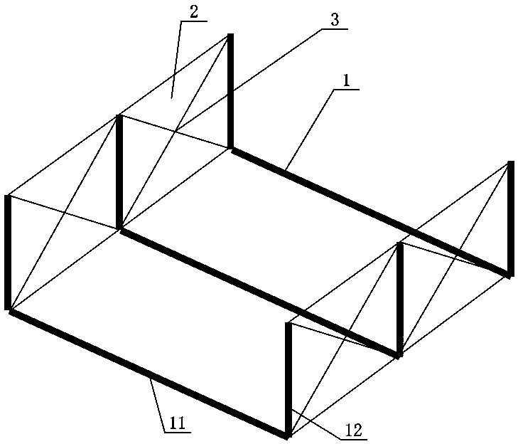
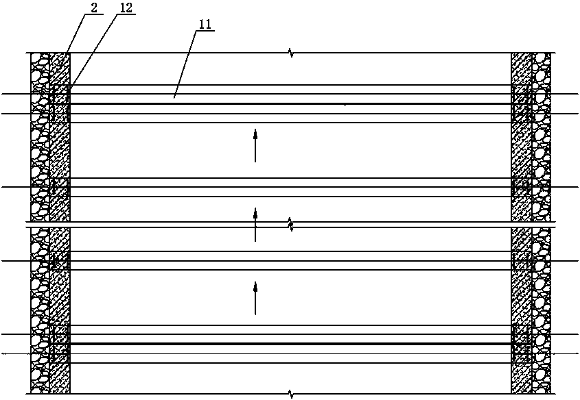
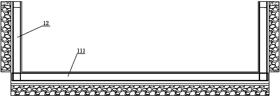
[0030] Figure 1 to Figure 6 It shows an embodiment of the narrow channel retaining wall reinforcement device of the present invention, which includes a plurality of U-shaped inverted door frames 1 adapted to the width and height of the river channel. Each U-shaped inverted door frame 1 is arranged at intervals along the river channel. The bottom of the U-shaped door frame 1 is buried in the river bed and is the same height as the bottom of the river bed. The two sides of each U-shaped door frame 1 are close to the old retaining walls on both sides of the river. Reinforced retaining wall 2 attached to the old retaining wall. During construction, first make a plurality of U-shaped inverted door frames 1 according to the width of the river channel and the height of the old retaining wall, set the layout spacing of each U-shaped inverte...


PUM


Abstract

The invention relates to a retaining wall reinforcing device and method for a narrow riverway. The retaining wall reinforcing device comprises a plurality of U-shaped inverted portals which are arranged at intervals along the riverway. The bottoms of the U-shaped inverted portals are as high as the bottom elevation of a riverbed. Each U-shaped inverted portal is provided with reinforcing walls along the two sides. The reinforcing method comprises the steps that S1, H-shaped steel bottom beams and H-shaped steel stand columns are blanked, and the multiple U-shaped inverted portals are manufactured; S2, trenches are dug along the riverbed; S3, the U-shaped inverted portals are hoisted to corresponding positions, and the H-shaped steel bottom beams are made to be located in the correspondingtrenches; S4, concrete is poured into all the trenches, so that H-shaped steel bottom beams encapsulated by the concrete are formed, and the top surface of the encapsulating concrete is as the bottomelevation of the riverbed; S5, reinforcing ribs are welded between the adjacent H-shaped steel stand columns; and S6, concrete pouring is completed to form a reinforcing retaining wall to encapsulatethe H-shaped steel stand columns, and drain holes are reserved in the pouring process. The reinforcing method and device have the advantages that the structure is stable and reliable, the service lifeis long, construction is convenient and fast, and flood discharge of the riverway and original landscapes on the river bank are not affected.

Description

technical field [0001] The invention mainly relates to a reinforcement technology for a retaining wall of a narrow river, in particular to a reinforcement device and a reinforcement method for a retaining wall of a narrow river. Background technique [0002] After the river retaining wall has been built and used for several years, affected by the subsidence of the foundation and the original construction quality, it is generally faced with reinforcement problems. In order to ensure the reinforcement effect of the retaining wall, the existing retaining wall reinforcement scheme generally needs to occupy a large area of ​​the river, especially in the river section. In the case of limited width, the flood discharge capacity of the river channel will be greatly reduced after the retaining wall is reinforced, and the flood risk will increase during the flood season, which will easily cause loss of life and property to the people on the river bank. The landscape effect has changed...

Claims


Application Information

Patent Timeline
Patent Type & Authority Applications(China)
IPC IPC(8): E02B3/06
CPCE02B3/066
Inventor 谢义华张建军唐雨邱艺文
Owner CHINA RAILWAY 12TH BUREAU GROUP 7TH CORPORATION LIMITED
Learn More