Beam-column connecting joint structure

A beam-column connection and node technology, applied in the direction of building structure, construction, etc., can solve the problems of small adjustment margin, large deflection of steel beams, and poor stiffness of steel frame structures against lateral movement, so as to reduce deflection and improve resistance The effect of lateral movement stiffness and guarantee of construction quality

Inactive Publication Date: 2018-07-27
CHINA 19TH METALLURGICAL CORP
View PDF9 Cites 5 Cited by
  • Summary
  • Abstract
  • Description
  • Claims
  • Application Information

AI Technical Summary

Problems solved by technology

However, during the construction process, it was found that the adjustment margin of the existing connection method is small, and more accurate production and installation precision control is required.
[0003] The existing patented technology CN201720444264.5 provides a new type of steel pipe beam-column connection node, which mainly includes a steel pipe column, at least one steel pipe beam and a double-shear connection plate connecting the steel pipe column and the steel pipe beam, which can solve the problem of large shopping malls and large Installation of steel structures in factory buildings and high-rise residential buildings, but the steel frame structure has poor stiffness against lateral movement, and the deflection of steel beams is relatively large

Method used


Image

  • Beam-column connecting joint structure
  • Beam-column connecting joint structure
  • Beam-column connecting joint structure

Examples


Embodiment Construction

[0020] The present invention will be further described below in conjunction with the accompanying drawings and embodiments.

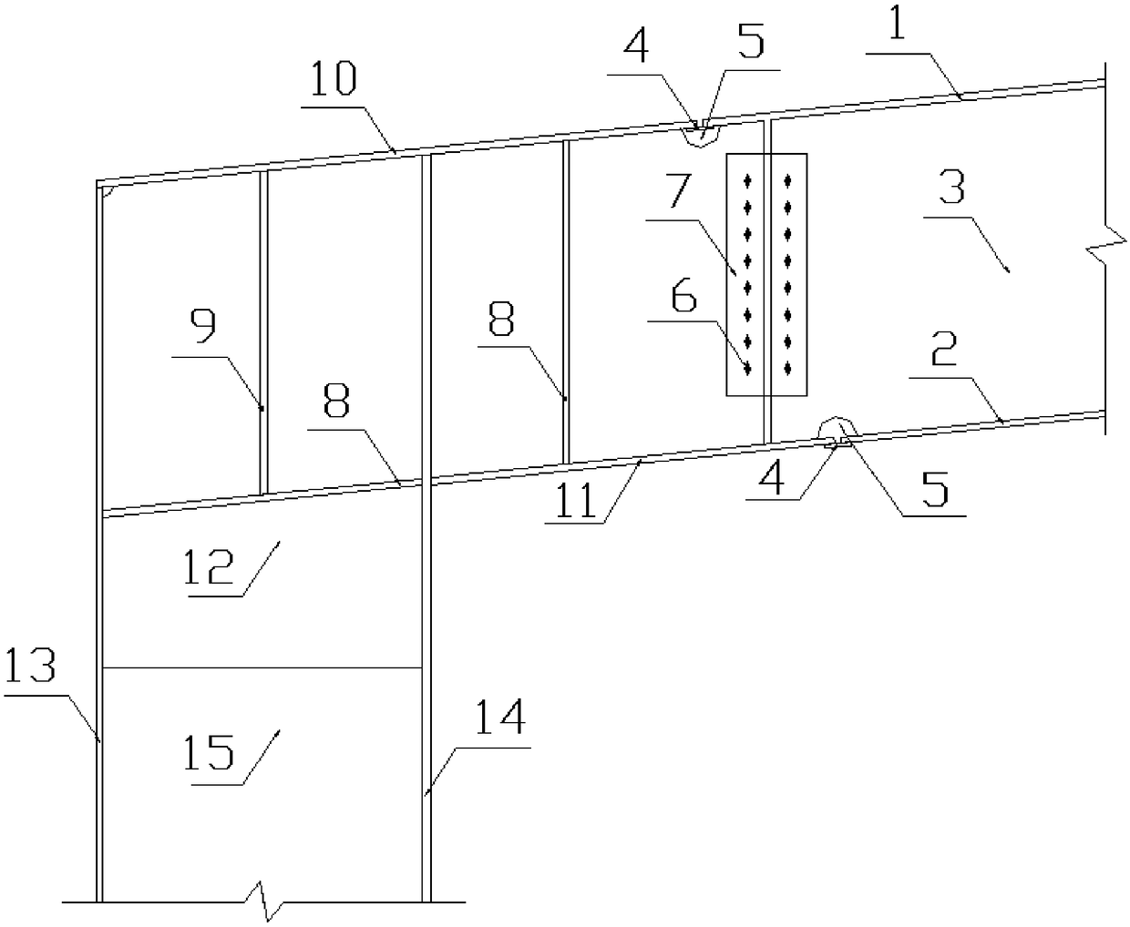
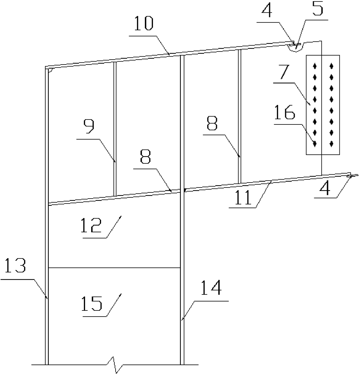
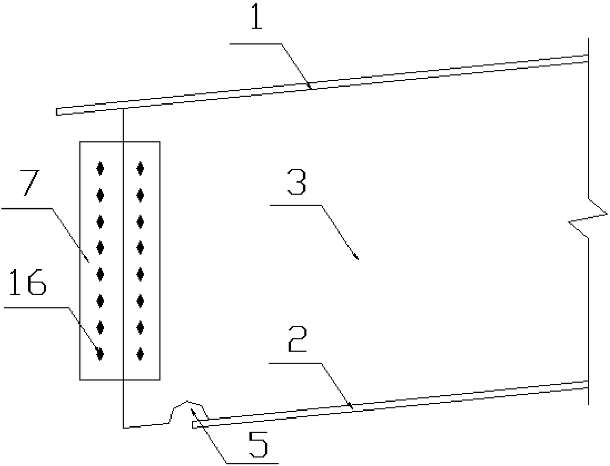
[0021] like Figure 1 to Figure 4 As shown, the present invention includes a steel column and a steel beam, and the steel column includes a column upper flange plate 10, a column corbel flange plate 11, a column upper web plate 12, a column outer flange plate 13, a column inner flange plate 14, The lower web 15 of the column, the outer flange plate 13 of the column, the inner flange plate 14 of the column, and the lower web 15 of the column constitute the main body of the H-shaped steel column;

[0022] The column upper web 12 is an inverted "L" shape, and the upper end of the column inner flange plate 14 has a slot for the overhang of the column upper web 12 to pass through. Welding and fixing, the top of the upper column web 12 is fixedly connected to the column upper flange plate 10, the bottom end of the overhanging part of the column upper web 12 ...


PUM


Abstract

The invention relates to a beam-column connecting joint structure, and belongs to the technical field of building steel structures. Steel columns are provided with cantilever beams each of an integralstructures, the steel columns and steel beams form Z-shaped butting joint, and the steel beams and the steel columns are connected at webs through the mode that two clamping plates are matched with high-strength bolts while the steel beams and the steel columns are welded at flange plates. According to the beam-column connecting joint structure, the shear bearing capacity of the splicing positions of steel column cantilevered parts and the steel beam can be ensured, the lateral resisting stiffness of a steel frame structure is improved, the deflection of the steel beams is decreased, accurateposition during high altitude hoisting of the steel beams in a construction site can also be ensured, on-site construction is facilitated, and the construction quality is ensured; and the joint structure form has the advantages of safety, reliability, clear force transmission and the like.

Description

technical field [0001] The invention relates to a beam-column connection node structure, which belongs to the technical field of building steel structures. Background technique [0002] At present, the common method of beam-to-column joint construction is as follows: set end plates at the ends of steel beams, and connect the end plates to the flange plates of steel columns with high-strength bolts. However, during the construction process, it was found that the adjustment margin of the existing connection method is small, and more accurate manufacturing and installation precision control is required. [0003] The existing patented technology CN201720444264.5 provides a new type of steel pipe beam-column connection node, which mainly includes a steel pipe column, at least one steel pipe beam and a double-shear connection plate connecting the steel pipe column and the steel pipe beam, which can solve the problem of large shopping malls and large The steel structure installati...

Claims


Application Information

Patent Timeline
Patent Type & Authority Applications(China)
IPC IPC(8): E04B1/24E04B1/58
CPCE04B1/2403E04B2001/2415
Inventor 刘昌文刘定凤甘立全石朝华
Owner CHINA 19TH METALLURGICAL CORP
Why Eureka
Try Eureka