
Phase change assisted heating tank-type heat collection system of solar water heater

A solar water heater and auxiliary heating technology, applied in the field of solar energy utilization, can solve the problems of low utilization rate of solar energy, great difficulty in vacuuming, low economic efficiency, etc., and achieve the effects of good social and economic benefits, increased utilization rate, and high heating efficiency

Active Publication Date: 2018-07-27
HEBEI UNIV OF TECH +1
View PDF12 Cites 2 Cited by
  • Summary
  • Abstract
  • Description
  • Claims
  • Application Information

AI Technical Summary

Problems solved by technology

[0004] The purpose of the present invention is to overcome the defects of low solar energy utilization rate, slow heating speed, difficult vacuuming, high cost and low economic efficiency in the prior art, and provide a trough solar water heater heat collection system with phase change auxiliary heating

Method used


Image

  • Phase change assisted heating tank-type heat collection system of solar water heater

Examples


Embodiment 1

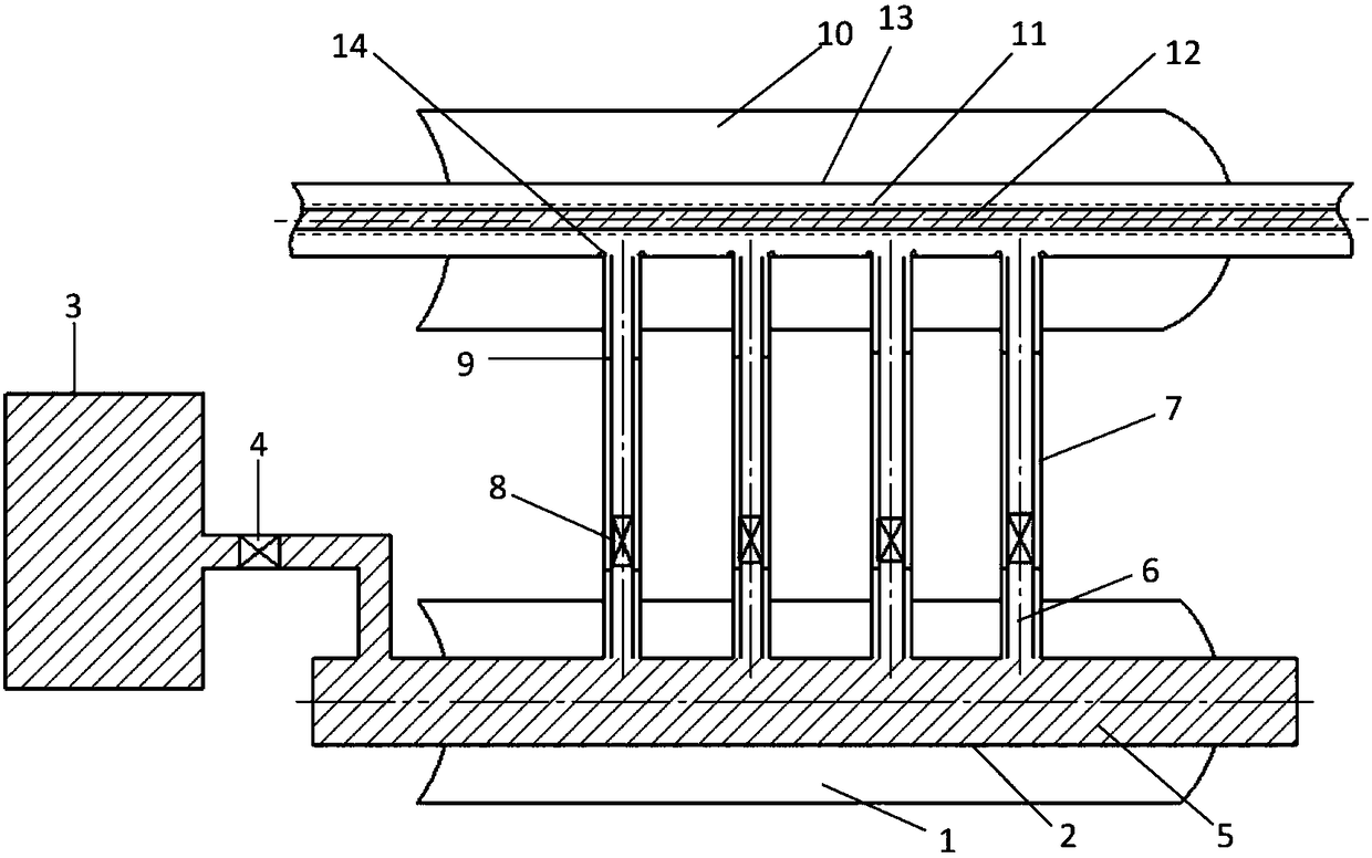
[0031] In this embodiment, a trough solar water heater heat collection system with phase change auxiliary heating includes an auxiliary heat collection device and a main heat collection device, and the auxiliary heat collection device transfers the collected solar energy to the main heat collection device through the phase change working medium 5 .

[0032] The auxiliary heat collection device includes an auxiliary heat collection tank 1, an auxiliary heat collection pipe 2, a phase change working medium storage tank 3, a valve 4, a standpipe, a throttle valve 8 and a connecting body 9, and the auxiliary heat collection pipe 2 is filled with The phase change working medium 5 is placed at the focal line of the auxiliary heat collecting tank 1 , the phase change working medium storage tank 3 is connected to the auxiliary heat collecting tube 2 , and the inner layer 6 of the standpipe is connected to the outer layer 7 of the standpipe through a connecting body 9 .

[0033] The ma...

Embodiment 2

[0039] In this embodiment, a phase-change auxiliary heating trough solar water heater heat collection system is connected to the same parts as in embodiment 1, the difference is that the auxiliary heat collection trough described in this embodiment is a trough concentrator with a length of 4m The cross-section of the auxiliary heat collecting tube is circular, the length is 4m, and the diameter is 1m; the number of the standpipes is 8, and the diameter of the outer layer of the standpipe is 100mm; the phase change working medium is water.

[0040] Taking Beijing as an example, the instantaneous solar radiation intensity in winter is about 200w / m 2 , the heat collecting area of ​​the main heat collecting device per unit length is about 2.25m 2 , The heat collection efficiency is about 63%.

[0041] When the temperature of the water in the auxiliary heat collecting tube is 4°C, the overall thermal efficiency increases by about 174.9%; if the temperature of the water in the auxi...


PUM


Abstract

The invention relates to a phase change assisted heating tank-type heat collection system of a solar water heater. The system comprises an auxiliary heat collecting device and a main heat collecting device; the auxiliary heat collecting device is used for transmitting collected solar energy to the main heat collecting device through a phase change working medium; the auxiliary heat collecting device comprises an auxiliary heat collecting tank, an auxiliary heat collecting tube, a phase change working medium storage tank, a vertical tube outer layer, a vertical tube inner layer, a throttle valve and a connector; the auxiliary heat collecting tube is filled with the phase change working medium and is horizontally arranged at a focal line of the auxiliary heat collecting tank; the two ends ofthe auxiliary heat collecting tube are closed; the phase change working medium storage tank is connected with the auxiliary heat collecting tube; and a position, corresponding to an opening in the bottom side of an outer layer glass tube, of the top of the auxiliary heat collecting tube is provided with a plurality of connecting openings. The system is simple in structure, can increase the utilization efficiency of the solar energy, increases the heating speed and the upper temperature limit of heating of the working medium and can also control the temperature within a safe range.

Description

technical field [0001] The invention relates to the field of solar energy utilization, in particular to a trough solar water heater heat collection system for phase change auxiliary heating. Background technique [0002] With the increasing shortage of energy worldwide and the seriousness of environmental pollution, more and more experts and scholars are turning their attention to the utilization of green energy such as solar energy, so the heat collection system of trough solar water heaters has emerged as the times require. [0003] The heat collection system of the trough solar water heater has a broad market prospect, and its main working range is 40-60°C. The main structure of the existing trough solar water heater heat collection system includes: trough concentrator, vacuum heat collection tube, etc., the utilization rate of solar energy is not high, the heat collection rate is low, and the upper limit of the temperature that can be achieved is lower (the existing temp...

Claims


Application Information

Patent Timeline
Patent Type & Authority Applications(China)
IPC IPC(8): F24S23/00F24S10/40F24S10/70F24S10/95F24S70/60
CPCY02E10/44
Inventor 王进刘娜娜翟郑佳雒婧王伟朱恒宣闵春华
Owner HEBEI UNIV OF TECH
Learn More