
Capacitive-resistant load high-current impact type direct-current relay

A DC relay and current impact technology, which is applied in the direction of electromagnetic relay, electromagnetic relay details, relay, etc., can solve the problems of relay contact separation failure, high overall cost, and out-of-control power supply cut-off, so as to improve the stability and reliability of use and use Long life, reduce the damage caused by the circuit, and avoid the effect of high current impact

Active Publication Date: 2018-07-27
ZHEJIANG YINGLUOHUA NEW ENERGY TECH CO LTD
View PDF6 Cites 4 Cited by
  • Summary
  • Abstract
  • Description
  • Claims
  • Application Information

AI Technical Summary

Problems solved by technology

[0006] The present invention solves the hazards of existing high-voltage DC relays used in new energy vehicles, which are easily impacted by instantaneous huge currents, resulting in contact adhesion, relay contact separation failure, and eventually resulting in power cut-off and loss of control. The circuit also has a complex circuit, a large overall volume, complex control, high overall cost, and inconvenient application and maintenance. A simple structure is provided, which can make the main relay close to the zero-crossing point of the current and voltage, effectively avoiding capacitive Load instantaneous high current impact, improve the stability, reliability and service life of the DC relay, reduce the damage to the circuit, and improve the overall safety and reliability of the circuit. Capacitive load high current impact DC relay

Method used


Image

  • Capacitive-resistant load high-current impact type direct-current relay
  • Capacitive-resistant load high-current impact type direct-current relay
  • Capacitive-resistant load high-current impact type direct-current relay

Examples


Embodiment Construction

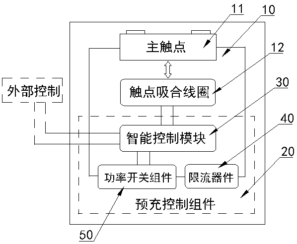
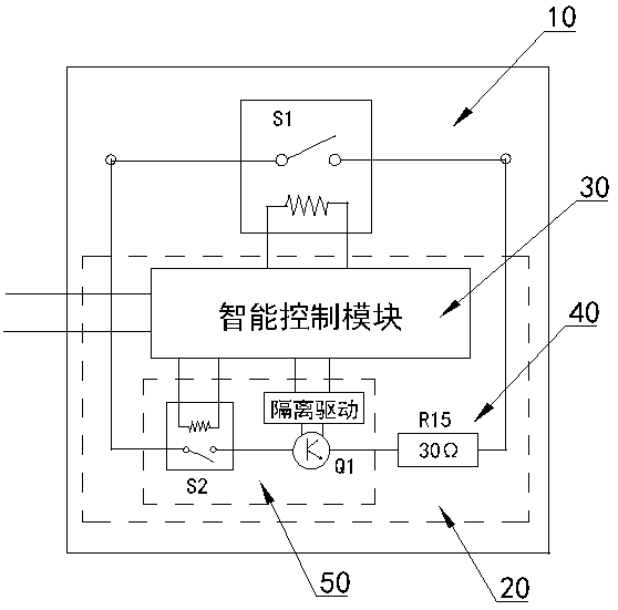
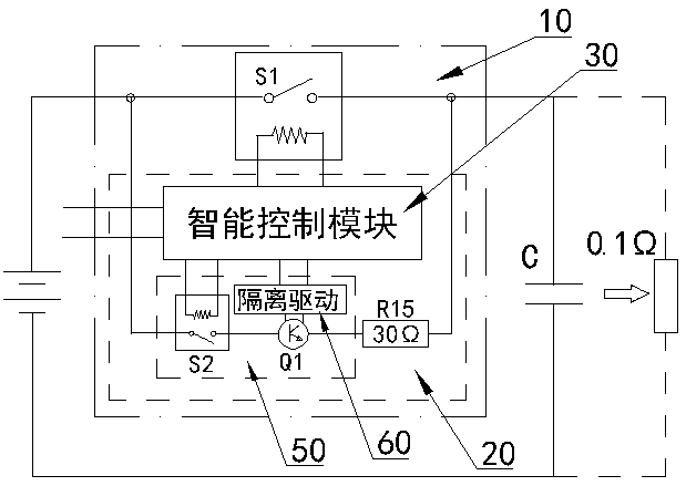
[0023] figure 1 , figure 2 , image 3 , Figure 4In the shown embodiment, a capacitive load high-current surge type DC relay includes a main relay S1 with a main contact 11 and a contact pull-in coil 12, and also includes a pre-charging control assembly 20, the pre-charging The charging control assembly 20 includes an intelligent control module 30, a power switch assembly 50 and a current limiting device 40, and the power switch assembly 50 includes a second relay S2, a first power switch tube Q1 and an isolation driver 60 module, the second relay coil and The intelligent control modules are electrically connected, and the first power switch tube Q1 is electrically connected to the intelligent control module 30 through the isolation drive 60 module. After the power switch assembly 50 and the current limiting device 40 are connected in series, both ends of the main contact 11 of the main relay S1 are connected to each other. Parallel electrical connection; when the relay i...


PUM


Abstract

The invention discloses a capacitive-resistant load high-current impact type direct-current relay. The relay comprises a main relay body and a precharge control assembly. The main relay body is provided with a main contact and a contact suction coil; the precharge control assembly comprises an intelligent control module, a power switch assembly body and a current limiting device; the power switchassembly body includes a second relay body, a first power switch tube and an isolated drive module; a second relay coil is electrically connected to the intelligent control module, the first power switch tube is electrically connected to the intelligent control module through the isolated drive module; the power switch assembly body and the current limiting device are in series connection and thenin electrically parallel connection with both ends of the main contact of the main relay body. The structure is simple, the main relay body can be turned on and off near a zero-crossing point of current voltage, the capacitive load instantaneous high-current impact is effectively avoided, the use stability and reliability of the direct-current relay is improved, the service life of the direct-current relay is prolonged, damage to the circuit is reduced, and the overall use safety and reliability of the circuit are improved.

Description

technical field [0001] The invention relates to a relay, in particular to a high-voltage DC relay used on a power battery. Background technique [0002] The power battery is the main energy supply system of pure electric vehicles. Generally, the combination of units is used to form a high-voltage battery pack (or HV power battery) to provide power for electric vehicles. A DC contactor is usually arranged between the battery system and the inverter of an electric vehicle, which is used to isolate the system when the system stops running, and to connect when the system is running. When the vehicle is shut down or fails, the energy storage system can be safely switched off. Separated from the vehicle electrical system, it functions as a circuit breaker. [0003] However, because the power devices driven by high-voltage variable-frequency drives work in the state of variable-frequency switching, which greatly interferes with the power supply circuit, in order to stabilize volta...

Claims


Application Information

Patent Timeline
IPC IPC(8): H01H47/00H01H47/02H01H50/02
Inventor 陈永辉宋文荣于荣爱杜德进周加城
Owner ZHEJIANG YINGLUOHUA NEW ENERGY TECH CO LTD
Learn More