Thermal superconducting fin radiator with phase change heat storage function

A phase-change heat storage and superconducting fin technology, which is applied in the field of heat transfer, can solve the problems such as the inability to meet the heat dissipation requirements of high heat flux density and high power modules, the temperature rise of radiators and power devices, and the inability to dissipate heat in time. The effect of achieving good work adaptability, strong heat dissipation capacity, and breaking through the limit of heat dissipation capacity limit

Active Publication Date: 2018-07-27
ZHEJIANG JIAXI TECH CO LTD
View PDF4 Cites 6 Cited by
  • Summary
  • Abstract
  • Description
  • Claims
  • Application Information

AI Technical Summary

Problems solved by technology

With the improvement of the performance of high-power devices, the increase of the heat flux density of a single device, and the improvement of the requirements for small size and light weight, the conventional aluminum heat sink can no longer meet the heat dissipation requirements of high-heat-flux high-power modules.
[0005] However, when the above-mentioned heat sink is used for heat dissipation of power devices, due to the poor heat dissipation effect, when the power device is short-term overloaded or fluctuates to generate a large amount of instantaneous heat, the heat cannot be dissipated in time, causing the temperature of the heat sink and power device to rise rapidly, thereby affecting Performance of Power Devices

Method used


Image

  • Thermal superconducting fin radiator with phase change heat storage function
  • Thermal superconducting fin radiator with phase change heat storage function
  • Thermal superconducting fin radiator with phase change heat storage function

Examples


Embodiment Construction

[0055] Embodiments of the present invention are described below through specific examples, and those skilled in the art can easily understand other advantages and effects of the present invention from the contents disclosed in this specification. The present invention can also be implemented or applied through other different specific implementation modes, and various modifications or changes can be made to the details in this specification based on different viewpoints and applications without departing from the spirit of the present invention.

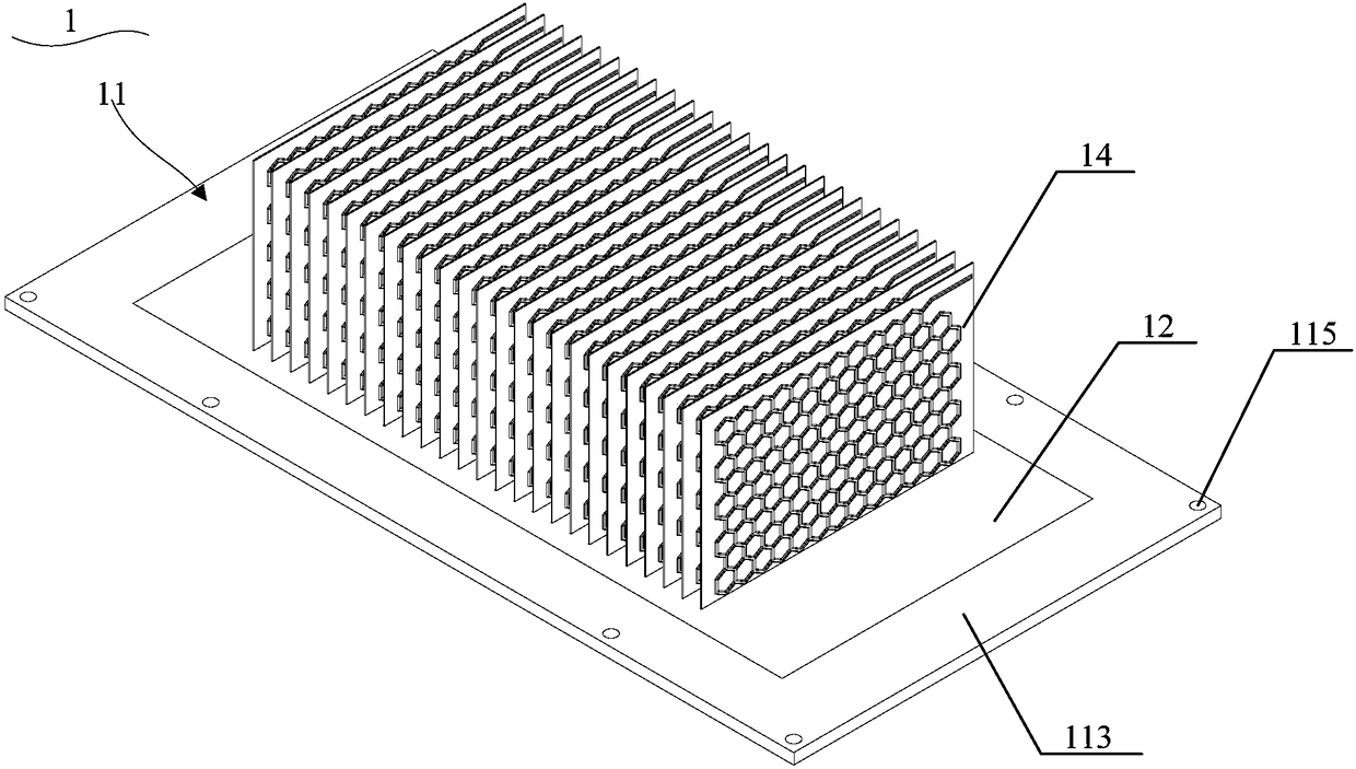
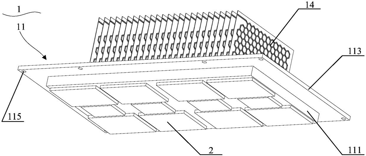
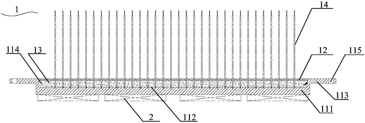
[0056] see Figure 1 to Figure 10 . It should be noted that the diagrams provided in this embodiment are only schematically illustrating the basic concept of the present invention, although only the components related to the present invention are shown in the diagrams rather than the number, shape and Dimensional drawing, the shape, quantity and proportion of each component can be changed arbitrarily during actual implementation, and ...


PUM

PropertyMeasurementUnit
thicknessaaaaaaaaaa
heightaaaaaaaaaa

Abstract

The invention provides a thermal superconducting fin radiator with a phase change heat storage function. The thermal superconducting fin radiator comprises a substrate, a cover plate, a phase change heat storage structure and thermal superconducting plate fins, wherein the substrate comprises a main body part; the main body part is provided with opposite first surface and second surface; a grooveis formed in the first surface of the main body part; the cover plate covers the groove and seals the groove; the groove is filled with the phase change heat storage structure; and one end of each thermal superconducting plate fin is inserted into the substrate at the bottom of the groove and the other end passes through the cover plate and extends to the upper part of the cover plate. The phase change heat storage structure is capable of absorbing and storing a large amount of transient heat caused by short-term overload or fluctuations of power devices and keeping the temperature of the radiator and the power devices stable. The thermal superconducting plate fins have the advantages of high cooling efficiency and small thermal resistance, and are not limited by low temperature.

Description

technical field [0001] The invention belongs to the technical field of heat transfer, in particular to a thermal superconducting fin radiator with phase change heat storage function. Background technique [0002] With the rapid development of power electronics technology, the requirements for modularization, integration, lightweight, low cost and high reliability are getting higher and higher. Therefore, in solar inverters, uninterruptible power supplies (UPS), charging piles, power MosFET (metal oxide semiconductor field effect transistor), Diode (diode), IGBT ( Insulated Gate Bipolar Transistors) and other power devices. As the integration of these power components is getting higher and higher, the power density is also increasing, and the heat generated by themselves during work is also increasing. If the heat generated by the power devices cannot be dissipated in time and quickly, it will lead to power failure. The temperature of the chip in the device rises, which wil...

Claims


Application Information

Patent Timeline
Patent Type & Authority Applications(China)
IPC IPC(8): H01L23/427H01L23/367
CPCH01L23/3672H01L23/427H01L23/4275
Inventor 仝爱星唐必洪曾巧
Owner ZHEJIANG JIAXI TECH CO LTD
Why Eureka
Try Eureka