Large and medium-sized kitchen waste heat recovery and utilization system

A waste heat recovery, large and medium-sized technology, applied in applications, heating methods, household heating, etc., can solve problems such as heat loss, difficulty in implementation, environmental heat pollution, etc., achieve high practicability and economy, avoid energy waste, cost cheap effect

Pending Publication Date: 2018-07-31
CHONGQING UNIV
View PDF8 Cites 2 Cited by
  • Summary
  • Abstract
  • Description
  • Claims
  • Application Information

AI Technical Summary

Problems solved by technology

[0003] The energy consumption plates in the kitchens of large and medium-sized canteens such as universities and restaurants are diverse (such as stoves, gas steamers, cold storage, air conditioning units, etc.), and the energy consumption is large. This part of heat enters the air, which not only causes certain thermal pollution to the environment , but also caused a large loss of heat and waste
At present, the energy saving of large and medium-sized kitchens in China is not taken seriously. The existing waste heat recovery technology is often only aimed at one of the specific energy consumption sectors, and there is a lack of comprehensive and efficient storage and utilization methods and equipment for other energy consumption sectors. Waste heat collection schemes for large and medium-sized kitchens are often expensive and difficult to implement, and fail to grasp the energy-saving issues of canteen kitchens as a whole. The actual application effect and feasibility need to be improved, resulting in the failure to store and recycle most of the waste heat in the kitchen use

Method used


Image

  • Large and medium-sized kitchen waste heat recovery and utilization system

Examples


Embodiment Construction

[0020] Below in conjunction with accompanying drawing and embodiment the present invention will be further described:

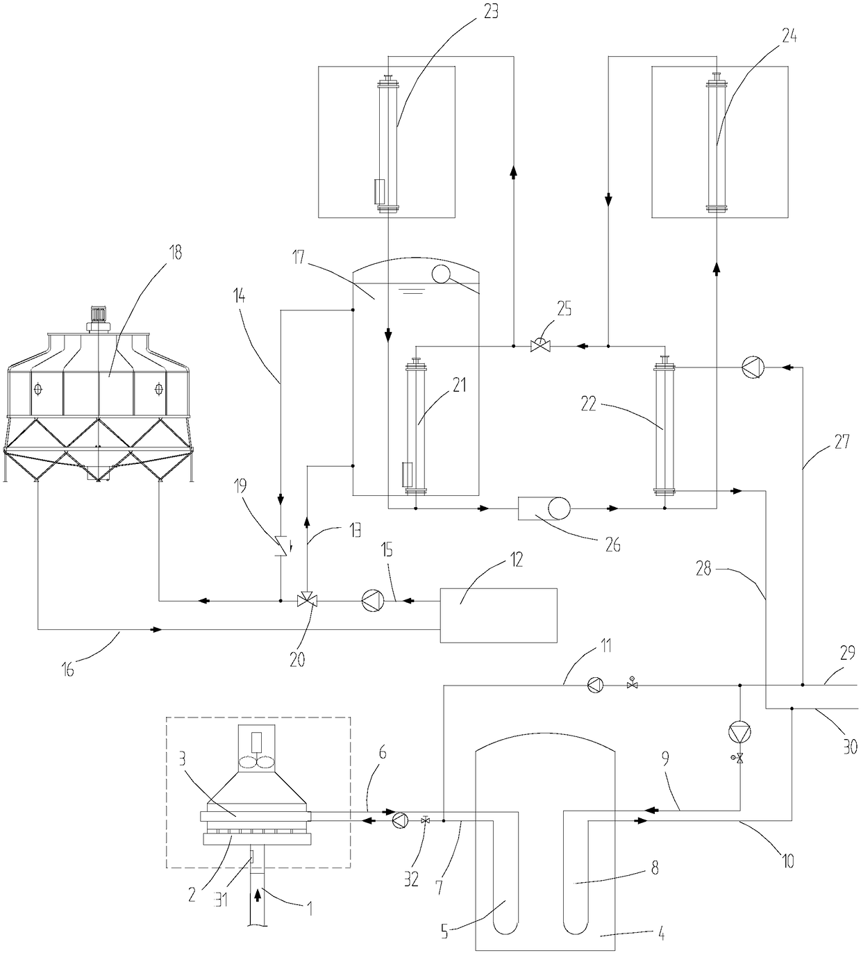
[0021] as attached figure 1 The shown large and medium-sized kitchen waste heat recovery system includes comprehensive recovery and utilization of the waste heat in the main flue, the waste heat generated by the refrigerator unit in the kitchen, and the waste heat of the air in the kitchen. The system of the present invention mainly includes smoke Gas heat recovery device and phase change heat storage tank 4, the phase change heat storage tank 4 is filled with No. 58 paraffin as phase change material, the phase change heat storage tank 4 is provided with a first water tank 5 and a second water tank 8, the second A water tank 5 communicates with the flue gas heat recovery device through the first water inlet pipe 6 and the first water outlet pipe 7 to form a circulating water circuit. The second water tank 8 communicates with the tap water supply pipe 29 throu...


PUM


Abstract

The invention discloses a large and medium-sized kitchen waste heat recovery and utilization system comprising a smoke heat recovery device and a phase change heat storage tank. A circulation waterwayis formed between a first water tank in the phase change heat storage tank and the smoke heat recovery device. A second water tank in the phase change heat storage tank communicates with a domestic hot water network. A refrigeration house refrigerator unit communicates with a cooling tower through a cooling water outlet pipeline and a cooling water inlet pipeline, and a circulation waterway is formed. A cooling water storage tank is in parallel connection with the cooling water outlet pipeline through a water storage tank water inlet pipe and a water storage tank water outlet pipe. The largeand medium-sized kitchen waste heat recovery and utilization system further comprises a dual-evaporator dual-condenser hot water heat pump unit comprising a first circulation waterway and a second circulation waterway. The first circulation waterway absorbs heat in the cooling water storage tank, and the heat serves as a domestic hot water source. After absorbed by the second circulation waterway,air heat in a kitchen serves as a dining room auxiliary heating source in winter. Through the large and medium-sized kitchen waste heat recovery and utilization system, waste heat of various energy consumption modules in the large and medium-sized kitchen is recovered simultaneously and then is utilized, and high practicability and economy are achieved.

Description

technical field [0001] The invention belongs to the technical field of waste heat recovery, in particular to a large and medium-sized kitchen waste heat recovery and utilization system. Background technique [0002] At present, with the development of low-carbon energy structure, the pace of my country's energy utilization is also accelerating. Increasing energy utilization and reducing energy consumption is one of the strategic goals of my country's sustainable development. However, my country's current energy status is as follows: the total amount of energy resources is abundant, the per capita share is small, the distribution is uneven, the development and utilization technology is immature, and the overall energy utilization rate is low. Therefore, improving the comprehensive utilization efficiency of energy is the top priority of current social development. [0003] The energy consumption plates in the kitchens of large and medium-sized canteens such as universities an...

Claims


Application Information

Patent Timeline
Patent Type & Authority Applications(China)
IPC IPC(8): F24C13/00F23J13/06F24H4/02
CPCF23J13/06F24C13/00F24H4/02Y02B30/12
Inventor 卢军黄书晨惠豫川卫俊宇罗天池李思琪黄小美
Owner CHONGQING UNIV
Why Eureka
Try Eureka