
Vacuum drying device

A technology of vacuum drying device and vacuum chamber, which is applied in the directions of drying gas arrangement, drying solid materials, drying solid materials without heating, etc. The effect of film formation uniformity, increased flow path, and improved uniformity

Active Publication Date: 2018-07-31
GUANGDONG JUHUA PRINTING DISPLAY TECH CO LTD
View PDF10 Cites 7 Cited by
  • Summary
  • Abstract
  • Description
  • Claims
  • Application Information

AI Technical Summary

Problems solved by technology

However, in the traditional vacuum dryer, the gas pipeline connected with the vacuum pump and the vacuum chamber have a large volume difference, which causes the airflow in the vacuum chamber to fluctuate violently and form a steep gradient of the airflow velocity. In turn, it is easy to drive the airflow in the samples such as ink to be dried to change drastically, which affects the uniformity of film formation

Method used


Image

  • Vacuum drying device
  • Vacuum drying device
  • Vacuum drying device

Examples


Embodiment Construction

[0033] In order to facilitate the understanding of the present invention, the present invention will be described more fully below with reference to the associated drawings. Preferred embodiments of the invention are shown in the accompanying drawings. However, the present invention can be embodied in many different forms and is not limited to the embodiments described herein. On the contrary, these embodiments are provided to make the understanding of the disclosure of the present invention more thorough and comprehensive.

[0034] It should be noted that when an element is referred to as being “fixed” to another element, it can be directly on the other element or there can also be an intervening element. When an element is referred to as being "connected to" another element, it can be directly connected to the other element or intervening elements may also be present.

[0035] Unless otherwise defined, all technical and scientific terms used herein have the same meaning as...


PUM


Abstract

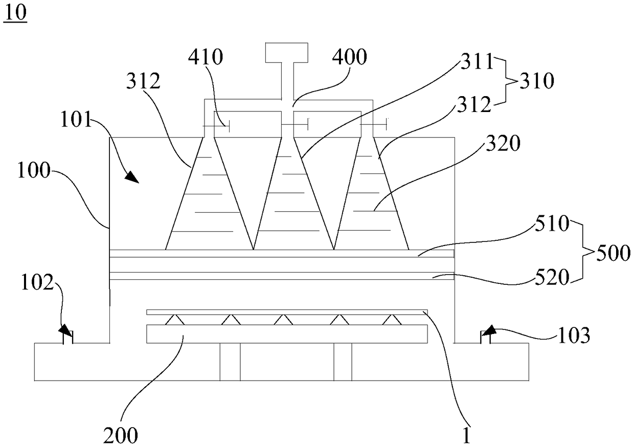
The invention relates to a vacuum drying device. The vacuum drying device comprises a drying chamber, a sample table and a flow stabilizing channel, wherein the drying chamber is provided with a vacuum cavity, the sample table is arranged in the vacuum cavity, the flow stabilizing channel is arranged in the vacuum cavity, one end of the flow stabilizing channel is used for communicating with an air extracting device, and the other end of the flow stabilizing channel is arranged towards the sample table and is provided with an airflow inlet. Compared with a conventional vacuum drier, a stable layer flow is formed on the surface of a sample by adopting the vacuum drying device, so that the situation of turbulence formed in a membrane layer or the situation that intermediate drying speed is small while the peripheral drying speed is high in the membrane layer can be avoided, water in ink and other materials to be volatilized can be uniformly volatilized as much as possible, the uniformityof membrane forming is effectively improved, and the performance of the device is further improved.

Description

technical field [0001] The invention relates to the technical field of drying equipment, in particular to a vacuum drying device. Background technique [0002] The use of solution processing to fabricate display devices including OLEDs and other light-emitting devices is an important direction for the future development of display technology due to its advantages of low cost, simple process, and easy realization of large-size displays. Among them, printing display is considered to be the most promising technology to realize low-cost preparation of large-size full-color OLED and other light-emitting devices. [0003] In the printing process, especially in inkjet printing, it is necessary to place printed ink and other materials in a vacuum dryer for vacuum drying. However, in the traditional vacuum dryer, the gas pipeline connected with the vacuum pump and the vacuum chamber have a large volume difference, which causes the airflow in the vacuum chamber to fluctuate violently...

Claims


Application Information

Patent Timeline
IPC IPC(8): F26B5/04F26B21/00
CPCF26B5/04F26B21/00
Inventor 刘新
Owner GUANGDONG JUHUA PRINTING DISPLAY TECH CO LTD
Learn More