
Ball return means with a fastening sleeve which can be mounted axially

A return device, ball technology, applied in the direction of transmission, steering mechanism, transportation and packaging, etc., can solve the jam, part of the pulley may reach between the main body and the deflector, prevent the ball nut from rotating, hinder, etc. question

Active Publication Date: 2018-07-31
THYSSENKRUPP PRESTA AG +1
View PDF12 Cites 0 Cited by
  • Summary
  • Abstract
  • Description
  • Claims
  • Application Information

AI Technical Summary

Problems solved by technology

The disadvantage of fastening the deflector directly to the toothed pulley is that if the toothed belt jams, part of the pulley may get between the body and the deflector and impede or prevent the ball nut from turning

Method used


Image

  • Ball return means with a fastening sleeve which can be mounted axially
  • Ball return means with a fastening sleeve which can be mounted axially
  • Ball return means with a fastening sleeve which can be mounted axially

Examples


Embodiment Construction

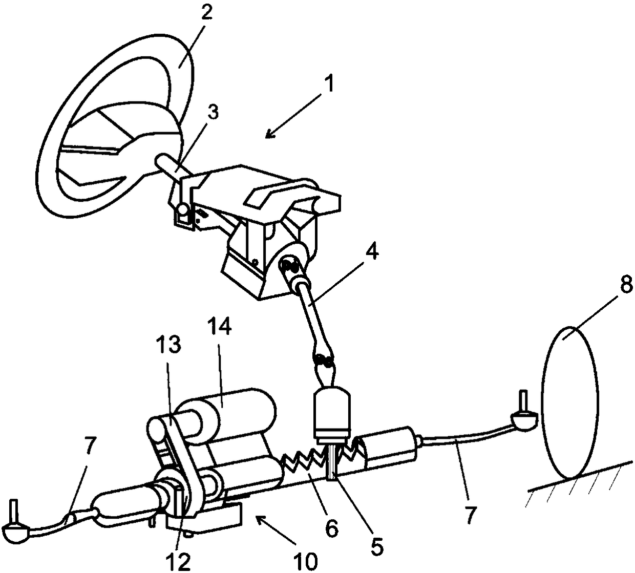
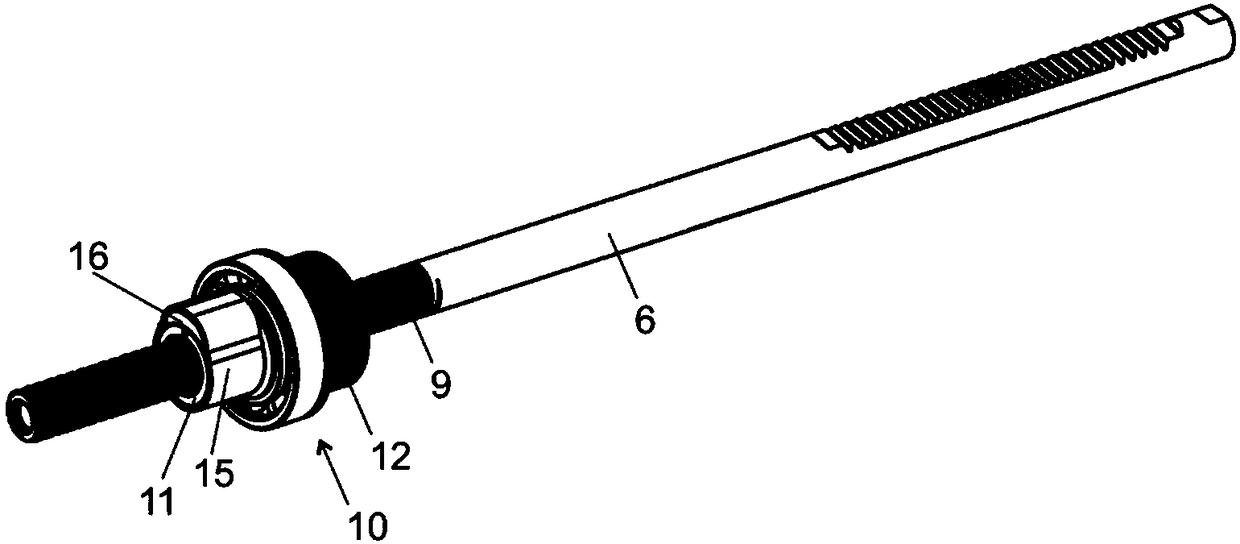
[0024] exist figure 1 In , an electromechanical motor vehicle steering system 1 is schematically shown having a steering wheel 2 coupled for common rotation to an upper steering shaft 3 and a lower steering shaft 4 . The lower steering shaft 4 is connected to a pinion 5 for common rotation. The pinion 5 meshes with the toothed segment of the rack 6 in a known manner. The rack 6 is mounted in the steering housing in such a way that it can move in the direction of its longitudinal axis. At its free end, the toothed rack 6 is connected to a steering rod 7 via a ball joint (not shown). The steering rod 7 is itself connected in a known manner to steered wheels 8 of the motor vehicle via a steering knuckle. Rotation of the steering wheel 2 through the connection of the steering shafts 3 , 4 and the pinion 5 leads to a longitudinal movement of the rack 6 and thus to a pivoting of the steering wheel 8 . On the outside of the rack 6 there is provided a ball screw thread 9 as part o...


PUM


Abstract

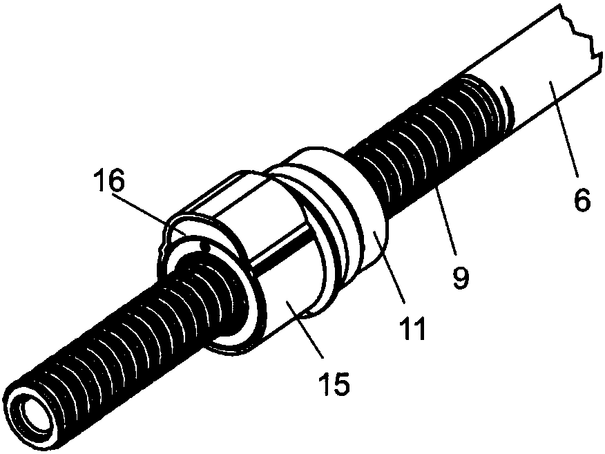
The invention relates to a power steering system (1), in particular for a motor vehicle, with a servomotor (14) which drives an axially displaceable rack (6) via a ball nut (11) which is mounted in abearing such that it can be rotated in a housing, wherein the ball nut (11) is in engagement with a threaded spindle (9) which is configured on the rack (6), and has a ball screw (17) on the inner side thereof for balls (18) to roll on, and with an external ball return means (20) which connects the start of the ball screw (17) to the end of the ball screw (17), in order to make endless circulationof the balls (18) possible, and with a deflecting body (16) and a sleeve (15), wherein a return channel (20') of the ball return means (20) is formed by way of the deflecting body (16) and the sleeve(15).

Description

technical field [0001] The invention relates to a power steering system having the features of the preamble of claim 1 and to a bushing for such a power steering system. Background technique [0002] Ball screw mechanisms are used to convert rotary motion into longitudinal motion or vice versa. In a steering system of a motor vehicle with an electric motor servo drive acting via a ball screw mechanism, the toothed rack has a section designed as a threaded shaft. A ball nut is arranged on the threaded shaft, and the ball nut is rotatably mounted on the threaded shaft by means of balls. A servo motor drives a ball nut via a gear mechanism to provide motor support for the longitudinal movement of the rack. A toothed rack with a section for the threaded shaft is accommodated in the housing. The ball nut is rotatably mounted in the housing by means of rolling bearings. A rolling bearing has an outer ring and an inner ring. [0003] DE 10 2010 054 134 discloses a plastic slee...

Claims


Application Information

Patent Timeline
Patent Type & Authority Applications(China)
IPC IPC(8): B62D5/04F16H25/22
CPCB62D5/0448F16H25/2214F16H25/2223
Inventor 安德拉斯·伊莱什沃尔弗拉姆·赖瑟
Owner THYSSENKRUPP PRESTA AG
Learn More