CO2 adsorption system and continuous CO2 adsorption method

An adsorption system and adsorbent technology, applied in chemical instruments and methods, separation methods, gas treatment, etc., can solve the problems of high energy consumption, low concentration, poor adsorption efficiency, etc.

Inactive Publication Date: 2018-08-03
CHNA ENERGY INVESTMENT CORP LTD +1
View PDF5 Cites 5 Cited by
  • Summary
  • Abstract
  • Description
  • Claims
  • Application Information

AI Technical Summary

Problems solved by technology

[0007] The purpose of the present invention is in order to overcome CO in prior art adsorption flue gas 2 The method and equipment have high energy consumption and desorbed CO 2 The problem of low concentration and poor adsorption efficiency provides CO 2 Adsorption system and CO 2 Continuous adsorption method, the adsorption unit of the system can make the catalyst packed in the cylinder continuously circulate through the CO2 under the drive of the rotating mechanism. 2 Adsorption, CO 2 desorption and cooling

Method used


Image

  • CO2 adsorption system and continuous CO2 adsorption method

Examples


Embodiment 1

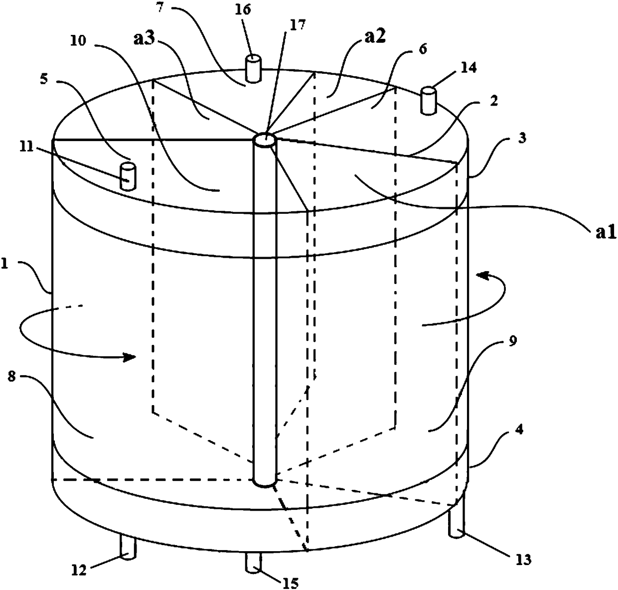
[0070] this invention figure 1 CO shown 2In the adsorption system, the cylinder is a cylinder with a diameter of 1m and a height of 0.8m with openings at both ends. There are 19 baffles inside to divide the internal space of the cylinder into 20 adsorbent filling areas.

[0071] The upper cover and the lower cover are provided with an adsorption zone, a desorption zone, a cooling zone, and buffer zones a1, a2 and a3, and the formed adsorption section accounts for 40% by volume, the desorption section accounts for 20% by volume, and the cooling section accounts for 20% by volume , the total volume of the buffer section accounts for 20% by volume.

[0072] The adsorption section contains 8 adsorbent filling areas, the desorption section contains 4 adsorbent filling areas, the cooling section contains 4 adsorbent filling areas, and the buffer section contains 4 adsorbent filling areas (among them, a1 contains 2 and a2 contains 1, a3 contains 1).

[0073] Barriers are set at bo...

Embodiment 2

[0082] this invention figure 1 CO shown 2 In the adsorption system, the cylinder is a cylinder with a diameter of 2m and a height of 1m with openings at both ends. There are 17 baffles inside to divide the internal space of the cylinder into 18 adsorbent filling areas.

[0083] The upper cover and the lower cover are provided with an adsorption area, a desorption area and a cooling area, and the formed adsorption section accounts for 50% by volume, the desorption section accounts for 20% by volume, the cooling section accounts for 15% by volume, and the total volume of the buffer section accounts for 15% by volume .

[0084] The adsorption section contains 8 adsorbent filling areas, the desorption section contains 3 adsorbent filling areas, the cooling section contains 3 adsorbent filling areas, and the buffer section contains 4 adsorbent filling areas (among them, a1 contains 2 and a2 contains 1, a3 contains 1).

[0085] Barriers are set at both ends of the cylinder with a...

Embodiment 3

[0094] this invention figure 1 CO shown 2 In the adsorption system, the cylinder is a cylinder with a diameter of 3m and a height of 2m with openings at both ends. There are 23 baffles inside to divide the internal space of the cylinder into 24 adsorbent filling areas.

[0095] The upper cover and the lower cover are provided with an adsorption area, a desorption area and a cooling area, and the formed adsorption section accounts for 45% by volume, the desorption section accounts for 20% by volume, the cooling section accounts for 15% by volume, and the total volume of the buffer section accounts for 20% by volume .

[0096] The adsorption section contains 11 adsorbent filling areas, the desorption section contains 4 adsorbent filling areas, the cooling section contains 3 adsorbent filling areas, and the buffer section contains 6 adsorbent filling areas (among them, a1 contains 2 and a2 contains 2, a3 contains 2).

[0097] Barriers are set at both ends of the cylinder with ...


PUM

PropertyMeasurementUnit
diameteraaaaaaaaaa
heightaaaaaaaaaa
diameteraaaaaaaaaa

Abstract

The invention relates to the field of CO2 adsorption, and discloses a CO2 adsorption system and a continuous CO2 adsorption method. The system comprises an adsorption unit, a gas treatment unit, a desorption treatment unit and a rotating mechanism; the adsorption unit comprises a cylinder body (1), a plurality of baffles (2) distributed in the cylinder body, an upper seal cover (3) of the cylinderbody and a lower seal cover (4) of the cylinder body; the cylinder body is a cylinder with openings at both ends, the baffles are distributed in accordance with the radial direction of the cross section of the cylinder body and extend to pass through the cylinder body along the central axis of the cylinder, and the internal space of the cylinder body is separated to form a plurality of adsorbentloading areas, wherein the adsorbent loading areas each have a fan-shaped cross section and do not communicate with each other; two ends of the cylinder are sealed by the upper seal cover and the lower seal cover respectively, a cylinder body space between the upper seal cover and the lower seal cover is divided into an adsorption section (8), a desorption section (9) and a cooling section (10); the rotating mechanism is used for rotating the cylinder body around the central axis of the cylinder, so that each adsorbent loading area passes through the adsorption section, the desorption sectionand the cooling section in turn. The energy consumption can be reduced, and the adsorption efficiency can be improved.

Description

technical field [0001] The present invention relates to CO 2 Adsorption field, specifically related to CO 2 Adsorption system and CO 2 continuous adsorption method. Background technique [0002] The global environmental problems centered on climate change are becoming more and more serious, and the control of greenhouse gas emissions has become the general consensus of the international community today. CO 2 Carbon Capture, Utilization & Storage (CCUS), as an important means to reduce greenhouse gas emissions from fossil fuels, will remain a global research hotspot. At present, a major bottleneck restricting the development of CCUS technology is CO 2 The cost of capture is too high, and new lower-cost CO 2 Capture technology is imminent. [0003] The survey found that the solvent method is currently the most important CO 2 Capture technology, but in order to reduce the viscosity of the solution and the volatility of organic amines, about 70% of water needs to be adde...

Claims


Application Information

Patent Timeline
Patent Type & Authority Applications(China)
IPC IPC(8): B01D53/06
CPCB01D53/06B01D2253/102B01D2257/504B01D2258/0283B01D2259/401Y02C20/40
Inventor 赵兴雷闫学良崔倩张峰龙银花孙永伟李永龙
Owner CHNA ENERGY INVESTMENT CORP LTD
Why Eureka
Try Eureka