Bevel gear transmission torque self-balancing shaftless ducted fan or propeller blades for aircraft

A technology for ducted fans and aircraft, which is applied in the field of bevel gear transmission torque self-balancing shaftless ducted fans or shaftless ducted blades for aircraft, which can solve the problem of large air circulation space in the hub, increased blade tip linear velocity, and reduced efficiency and other issues, to achieve the effect of reducing disturbance and wind resistance, reducing disturbance turbulence, and improving lift

Pending Publication Date: 2018-08-03
长沙紫宸科技开发有限公司
View PDF1 Cites 5 Cited by
  • Summary
  • Abstract
  • Description
  • Claims
  • Application Information

AI Technical Summary

Problems solved by technology

But because the known ducted fans or blades all work in the way that the central shaft drives the hub to drive the blades to rotate, the existing axial ducted fans or blades have the following disadvantages: one is that the existence of the hub occupies a large The air circulation space hinders the flow of air flow. In order to ensure that the fan has a sufficient flow area when it is working, it is usually designed to increase the outer diameter of the blade, but the increase in the outer diameter of the blade will increase the linear velocity of the blade tip, which will cause noise. increase, and the blade tip is easily deformed under aerodynamic action, resulting in a decrease in efficiency; second, boundary layer separation and secondary flow often exist at the connection between the traditional fan hub and the blade, which affects the energy conversion effect and reduces the efficiency of the blade. Work efficiency; third, in order to prevent the blade tip from rubbing against the ducted air duct, there is usually a gap between the two, that is, the blade tip gap. During operation, the high-pressure gas on the blade pressure surface will bypass the blade tip gap It flows into the suction surface of the blade, which not only produces flow leakage and volume loss, but also destroys the stability of the flow field, which ultimately leads to a decrease in the efficiency of the whole machine
In order to solve the above problems, scientists have carried out a lot of technological innovation and improvement, especially in the design of the fan, such as the application number 201710914763.0 Chinese patent application discloses a rack and pinion driven shaftless fan, the technical solution of which is adopted The motor drives the rack and pinion, and the rack and pinion drive the rotor parts with sliding friction to rotate from the rim. Although the central shaft and the hub are reduced, the mechanical design of the fan requires a separate lubrication device that is complicated and difficult to maintain. The relative installation position of the motor and the fan is inconvenient to use and has a large volume, and it cannot provide the aircraft with an automatically balanced torque. Although this technical solution provides a new solution for the design of the fan, it is only a shaftless fan technology. scheme, its structure and characteristics determine that it cannot be used as a ducted fan or blade of an aircraft

Method used


Image

  • Bevel gear transmission torque self-balancing shaftless ducted fan or propeller blades for aircraft
  • Bevel gear transmission torque self-balancing shaftless ducted fan or propeller blades for aircraft
  • Bevel gear transmission torque self-balancing shaftless ducted fan or propeller blades for aircraft

Examples


Embodiment 1

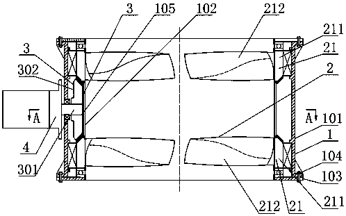
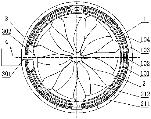
[0031] refer to figure 1 and figure 2 , a self-balancing shaftless ducted fan with bevel gear transmission torque for an aircraft, comprising a ducted cylinder frame 1, a group of reverse shaftless fans 2 and a transmission mechanism 3, and the reverse shaftless fan 2 and the transmission mechanism 3 are installed In the duct holder 1, the transmission mechanism 3 is connected with the reverse shaftless fan 2 through gears to form a shaftless ducted fan.

[0032] The duct holder 1 includes a duct holder 101, a duct inner cylinder 102 and an annular end cover 103. The duct holder 101 is a mounting bracket for the reverse shaftless fan 2 and the transmission mechanism 3. The annular end cover 103 It is connected with the end of the duct frame 101 through connecting bolts 104, and is used to fix the reverse shaftless fan 2 and prevent it from sliding axially.

[0033] The set of reverse shaftless fans 2 includes two shaftless fans 21 that can rotate in reverse, and the shaftle...

Embodiment 2

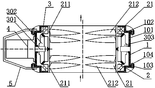
[0040] refer to image 3 , a self-balancing shaftless ducted fan with bevel gear transmission torque for aircraft, the main difference from Embodiment 1 is that this embodiment uses annular angular contact bearings instead of radial bearings and axial bearings as the reverse shaftless fan 2 Install the bracket, and the annular end cover 103 is welded and folded at this time;

[0041] The two toothed cylindrical swivels 211 of the reverse shaftless fan 2 of the present embodiment are T-shaped rings, and the surface near the fan port of the toothed cylindrical swivel 211 is connected with the annular end cover 103 through the annular angular contact bearing, the gear It meshes with the main bevel gear 302, and at the same time, two toothed cylindrical swivels 211 are connected by plane bearings to form the duct inner cylinder 102;

[0042] The blades 212 of this embodiment are of two stages, and are evenly fixed on the inner surface of the toothed cylindrical swivel 211;

[00...

Embodiment 3

[0046] refer to Figure 4 , a self-balancing shaftless ducted fan with bevel gear transmission torque for an aircraft, the main difference from Embodiment 1 is that the toothed swivel of this embodiment is a toothed annular swivel 221, and it is also provided with a power unit 4 synchronous The second power unit 4' in operation, the second power unit 4' drives the toothed annular swivel 221 through the transition bevel gear 303 that is symmetrical with the main bevel gear 302 to provide more sufficient power and increase the power of the shaftless ducted fan for the aircraft The installation position of the power unit 4 and the second power unit 4' is also provided with a swing device 5, the swing device 5 is connected with the duct frame 101, and the shaftless ducted fan of the aircraft can be adjusted by synchronously rotating the swing device 5. Lift direction, realize the control of aircraft speed;

[0047] Each shaftless fan 21 of this embodiment is also provided with a ...


PUM


Abstract

The invention provides a bevel-gear-transmission torque self-balancing shaftless ducted fan or propeller blades for an aircraft. The bevel-gear-transmission torque self-balancing shaftless ducted fancomprises a duct cylinder frame, at least one set of reverse shaftless fans or the shaftless propeller blades, and transmission mechanisms; the reverse shaftless fans or the shaftless propeller bladesand the transmission mechanisms are mounted in the duct cylinder frame; and the transmission mechanisms are connected with the reverse shaftless fans or the shaftless propeller blades through gears to form the shaftless ducted fan or the shaftless ducted propeller blades. According to the bevel-gear-transmission torque self-balancing shaftless ducted fan or propeller blades, the structure is simple, and mounting and using are convenient; and the bevel-gear-transmission torque self-balancing shaftless ducted fan or propeller blades are suitable for being used for the current aircraft which isapplied increasingly and widely, and especially suitable for a manned aircraft requiring low noise and high lift or thrust and having self-balancing torque.

Description

technical field [0001] The invention relates to the technical field of aircraft power, in particular to a self-balancing shaftless ducted fan or shaftless ducted blade for an aircraft with bevel gear transmission torque. Background technique [0002] Today, propellers or ducted fans have been widely used in various types of aircraft. In order to increase the lift of the blades or reduce noise, various forms of ducted fans or propellers have emerged as aircraft power designs. But because the known ducted fans or blades all work in the way that the central shaft drives the hub to drive the blades to rotate, the existing axial ducted fans or blades have the following disadvantages: one is that the existence of the hub occupies a large The air circulation space hinders the flow of air flow. In order to ensure that the fan has a sufficient flow area when it is working, it is usually designed to increase the outer diameter of the blade, but the increase in the outer diameter of th...

Claims


Application Information

Patent Timeline
Patent Type & Authority Applications(China)
IPC IPC(8): F02K5/00F04D25/08F04D25/16F04D29/32F04D29/34F04D29/66F04D29/54F04D27/00H02K7/14
CPCH02K7/14F02K5/00F04D25/0606F04D25/08F04D25/166F04D27/002F04D29/325F04D29/34F04D29/541F04D29/666F04D25/02F04D19/024F04D19/007B64D35/06B64C11/48B64C11/001F01D5/03F05D2260/4031F03D9/32F03D3/04F03D3/062F05B2240/923F05B2240/941F03D15/00F05B2260/5032Y02E10/74Y02E10/728
Inventor 尹小林赵海洋
Owner 长沙紫宸科技开发有限公司
Why Eureka
Try Eureka