
Image processing method and device and electronic equipment

An image processing and processing area technology, applied in the field of image processing, can solve the problems of not considering the deformation area, increasing the amount of calculation, reducing the real-time processing of micro-shaping special effects, etc.

Active Publication Date: 2018-08-03
BEIJING QIHOO TECH CO LTD
View PDF5 Cites 2 Cited by
  • Summary
  • Abstract
  • Description
  • Claims
  • Application Information

AI Technical Summary

Problems solved by technology

[0003] However, in the process of implementing the present invention, the inventor found that the above-mentioned methods in the prior art have at least the following problems: In the above-mentioned application scenarios, the current micro-plastic special effect processing is often applicable to the face in the image is a frontal face. However, when the face has a relatively large lateral angle, the processed face will have local deformities such as depressions or bulges, and the effect of micro-plastic special effects is poor; in addition, micro-plastic special effects often cause All pixels in the image are processed without considering the actual deformation area, so some pixels that do not need to be processed are also processed, which increases a lot of extra calculations and reduces the real-time performance of micro-shaping special effects processing
In summary, there is still no technical solution that can well solve the above problems in the prior art

Method used


Image

  • Image processing method and device and electronic equipment
  • Image processing method and device and electronic equipment
  • Image processing method and device and electronic equipment

Examples


Embodiment Construction

[0078] Exemplary embodiments of the present disclosure will be described in more detail below with reference to the accompanying drawings. Although exemplary embodiments of the present disclosure are shown in the drawings, it should be understood that the present disclosure may be embodied in various forms and should not be limited by the embodiments set forth herein. Rather, these embodiments are provided for more thorough understanding of the present disclosure and to fully convey the scope of the present disclosure to those skilled in the art.

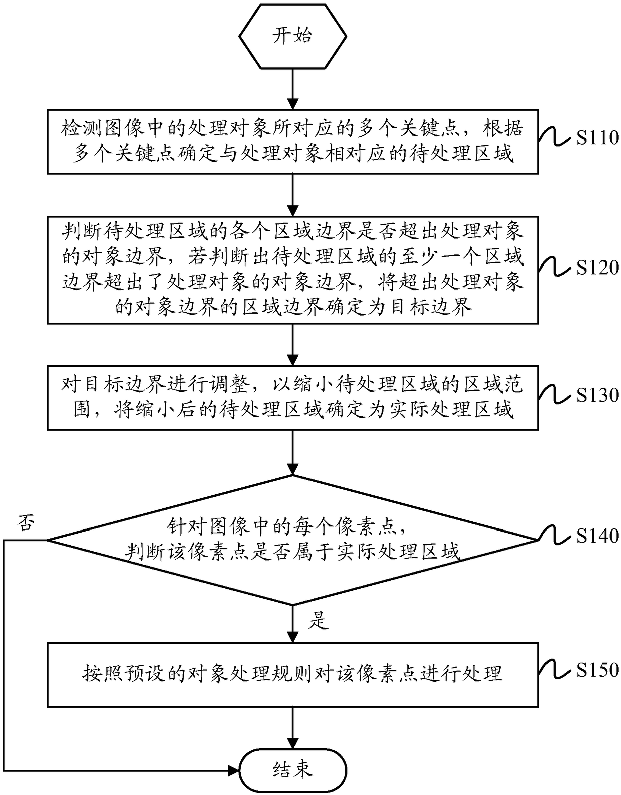
[0079] figure 1 A schematic flowchart of an image processing method according to an embodiment of the present invention is shown. Such as figure 1 As shown, the method includes the following steps:

[0080] Step S110 , detecting multiple key points corresponding to the processing object in the image, and determining a region to be processed corresponding to the processing object according to the multiple key points.

[0081] Whe...


PUM


Abstract

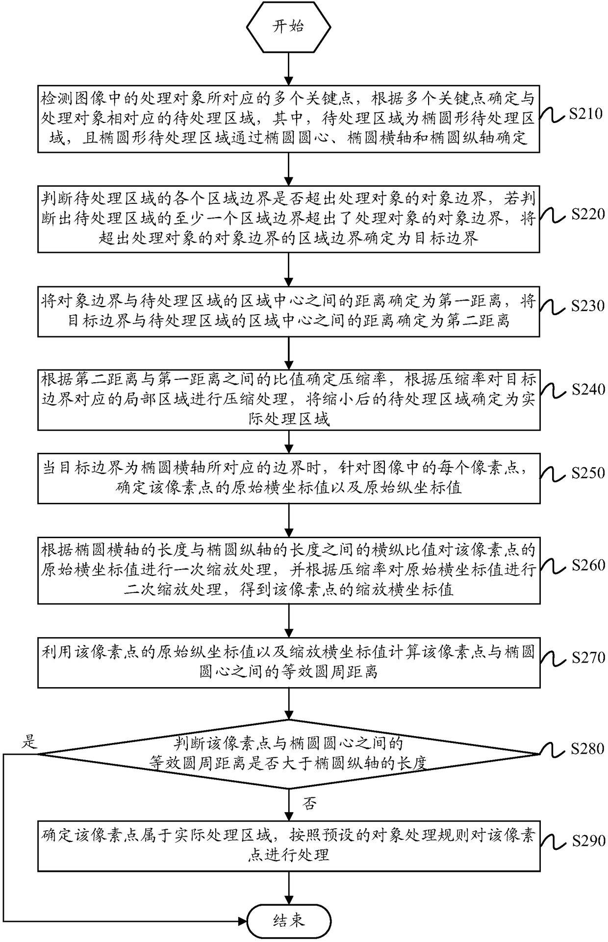
The invention discloses an image processing method and device and electronic equipment. The method comprises the steps of detecting multiple key points corresponding to a processing object in an image, and according to the key points, determining a to-be-processed area corresponding to the processing object; judging whether all area boundaries of the to-be-processed area go beyond an object boundary of the processing object or not; if yes, determining the area boundaries going beyond the object boundary of the processing object as target boundaries; adjusting the target boundaries to shrink the area range of the to-be-processed area, and determining the shrunk to-be-processed area as an actual processing area; aiming at each pixel point in the image, judging whether the pixel point belongsto the actual processing area or not, if yes, processing the pixel point according to a preset object processing rule. As can be known, by means of the image processing method, it can be guaranteed that the boundaries of the actual processing area do not go beyond the boundary of the processing object, and the pixel points which need to be processed are divided through the actual processing area.In this way, the calculation amount can be reduced, and the processing speed is increased.

Description

technical field [0001] The present invention relates to the technical field of image processing, in particular to an image processing method, device and electronic equipment. Background technique [0002] With the development of computer image processing technology, image beautification has become more and more convenient and popular. Image beautification technology is applied to scenes such as image post-processing, video live broadcast, and recorded video, such as micro-shaping special effects processing, micro-shaping special effects processing is It is only processed for the pixels in some areas of the image. For example, in the application scenario of micro-reshaping special effects processing on the face image, including face-lifting, enlarging eyes, raising the bridge of the nose, shrinking the wings of the nose, etc., it can improve Therefore, micro-shaping special effects processing in image beautification has been widely concerned and favored by people. [0003] H...

Claims


Application Information

Patent Timeline
IPC IPC(8): G06T3/00G06T7/13G06T7/73
CPCG06T7/13G06T7/73G06T2207/10004G06T3/04
Inventor 李艳杰眭一帆
Owner BEIJING QIHOO TECH CO LTD
Learn More