LED drive circuit with adjustable current

A technology of LED drive and LED lamp group, applied in the direction of electric light source, electrical components, electroluminescent light source, etc., can solve the problems of large current fluctuations flowing through the drive circuit, poor response speed, LED flickering, etc., to achieve Effects of improving efficiency and stability, reducing spikes and glitches, and accelerating turn-off time

Inactive Publication Date: 2018-08-03
UNIV OF SHANGHAI FOR SCI & TECH
View PDF6 Cites 6 Cited by
  • Summary
  • Abstract
  • Description
  • Claims
  • Application Information

AI Technical Summary

Problems solved by technology

At present, various LED driver chips are widely used. One disadvantage of the LED driver chip driver circuit is that it cannot be adjusted to a very low current. For some displays with high display requirements, it is sometimes required to achieve very low brightness. It is necessary to adjust the current of the LED drive circuit to a very low level. The present invention proposes a linear constant current feedback circuit to drive the LED. For the linear constant current feedback circuit, it is necessary to use PWM to drive the MOS tube switch to achieve constant current. , in practical applications, due to the interference of external power supply or the influence of device parameters, there will be spikes and burrs in the front-stage drive waveform of the MOS tube, and if the response speed of the MOS tube used is not very good, PWM directly drives the MOS tube. The slow off speed affects the efficiency of the drive circuit, and this effect is more obvious in the case of using high-frequency PWM to drive the MOS tube
When using high-frequency PWM to drive the MOS tube, if the MOS tube cannot be turned off in time, it will affect the stability of the circuit, and the current flowing through the drive circuit may fluctuate greatly, causing the LED to flicker.

Method used


Image

  • LED drive circuit with adjustable current
  • LED drive circuit with adjustable current

Examples


Embodiment Construction

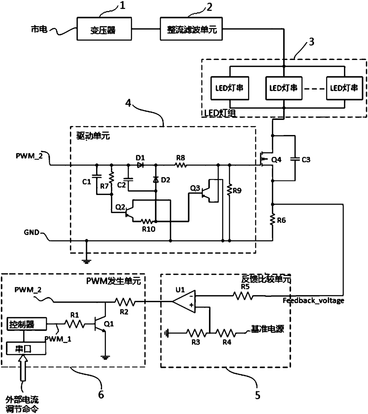
[0010] Such as figure 1 The schematic diagram of the LED drive circuit with adjustable current is shown, including transformer 1, rectification and filtering unit 2, LED lamp group 3, MOS tube Q4, drive unit 4, feedback comparison unit 5 and PWM generation unit 6, and the mains power is stepped down by transformer 1 The output is to the rectification and filtering unit 2, and the rectification and filtering unit outputs a DC power supply connected to the positive pole of the LED lamp group 3 to supply power to the LED lamp group 3. The LED lamp group 3 is composed of multiple LED lamps connected in parallel, and the negative pole of the LED lamp group 3 is connected to the MOS tube Q4 The drain and the source of the MOS transistor Q4 are connected to the feedback comparison unit 5 through the sampling resistor R6, and the MOS transistor Q4, the sampling resistor R6 and the feedback comparison unit 5 form a linear constant current feedback circuit to realize the constant current...


PUM


Abstract

The present invention relates to a LED drive circuit with an adjustable current. Electric supply is subjected to voltage reduction by a transformer and then is output to a rectification filtering unit, the rectification filtering unit outputs the electric supply to a LED lamp set for power supply, a negative pole of the LED lamp set is connected with an MOS tube Q4, a sampling resistor R6 and a feedback comparison unit in order to achieve constant current of a LED drive circuit, the feedback comparison unit outputs a current to a PWM generation unit, the PWM generation unit outputs PWM waveform signals to a drive unit, the drive unit improves the switching motion response speed for drive of the MOS tube Q4, a controller in the PWM generation unit performs processing of the external currentadjusting command from a serial port, the frequency of outputting PWM signals by the PWM generation unit is regulated to achieve adjustment of the size of a current of the LED lamp set. The LED drivecircuit with an adjustable current can achieve regulation in a range from none to a set maximum value, the provided drive unit circuit can effectively accelerate the on-off time of the MOS tube and can eliminate the peak and the burr of the gate waveform of the MOS tube so as to greatly improve the efficiency and the stability of the LED drive circuit.

Description

technical field [0001] The invention relates to an LED driving technology, in particular to an adjustable current LED driving circuit. Background technique [0002] LED lights are often used as the backlight design of liquid crystal displays. In practical applications, since the brightness of the display needs to be adjusted, an LED drive circuit that can adjust the current is required. At present, various LED driver chips are widely used. One disadvantage of the LED driver chip driver circuit is that it cannot be adjusted to a very low current. For some displays with high display requirements, it is sometimes required to achieve very low brightness. It is necessary to adjust the current of the LED drive circuit to a very low level. The present invention proposes a linear constant current feedback circuit to drive the LED. For the linear constant current feedback circuit, it is necessary to use PWM to drive the MOS tube switch to achieve constant current. , in practical app...

Claims


Application Information

Patent Timeline
Patent Type & Authority Applications(China)
IPC IPC(8): H05B33/08H05B44/00
CPCH05B45/37
Inventor 杨国良叶小林卢宏孙鹏赵新坤
Owner UNIV OF SHANGHAI FOR SCI & TECH
Why Eureka
Try Eureka