Eureka AIR delivers breakthrough ideas for toughest innovation challenges, trusted by R&D personnel around the world.

Combined rigid frame steel plate girder-pier girder solid structure

A steel plate girder and structure construction technology, which is applied in the field of composite steel plate girder bridge pier girder solid structure, can solve the problems of high maintenance cost, poor seismic performance, cracking and mid-span deflection, etc., and achieve low requirements and light weight Effect

Inactive Publication Date: 2018-08-07
ZHEJIANG PROVINCIAL INST OF COMM PLANNING DESIGN & RES CO LTD
View PDF8 Cites 3 Cited by
  • Summary
  • Abstract
  • Description
  • Claims
  • Application Information

AI Technical Summary

Problems solved by technology

[0006] In view of the above, the present invention provides a combined rigid steel plate girder bridge pier girder structure, which connects the steel plate girder and the concrete pier through a perforated steel plate, which has a simple structure, reasonable force and reliable force transmission, and can meet normal use requirements. It meets various requirements under the bearing limit state, improves the spanning capacity of the bridge while reducing its own weight, and effectively solves the web concrete cracking and mid-span deflection under the long-term load of the existing concrete rigid frame bridge, and the existing steel plate continuous beam support. Prominent problems such as high maintenance costs in the later stage of the seat, cumbersome cantilever construction procedures, and poor seismic performance

Method used


Image

  • Combined rigid frame steel plate girder-pier girder solid structure
  • Combined rigid frame steel plate girder-pier girder solid structure
  • Combined rigid frame steel plate girder-pier girder solid structure

Examples


Embodiment Construction

[0028] In order to describe the present invention more specifically, the technical solutions of the present invention will be described in detail below in conjunction with the accompanying drawings and specific embodiments.

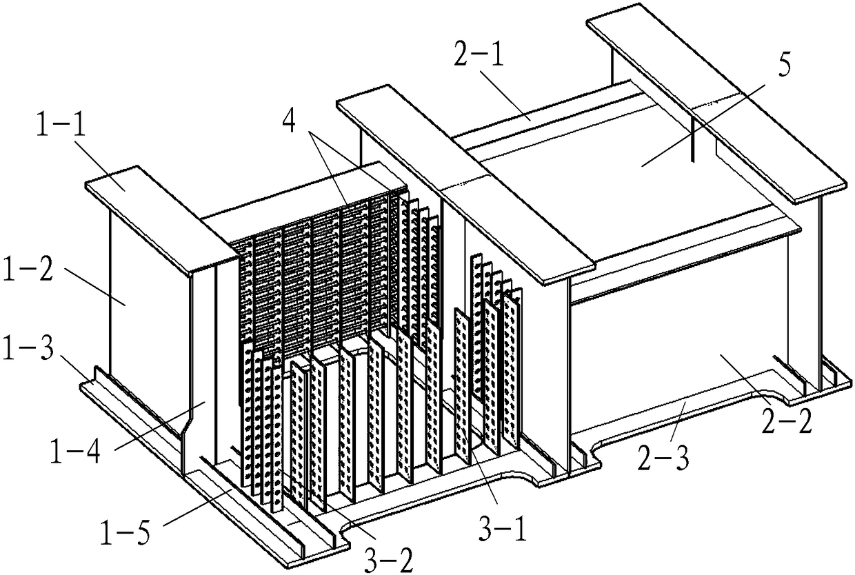
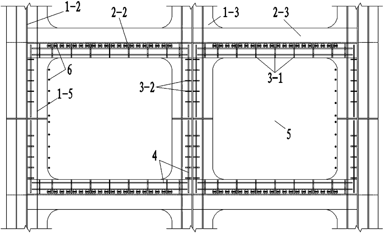
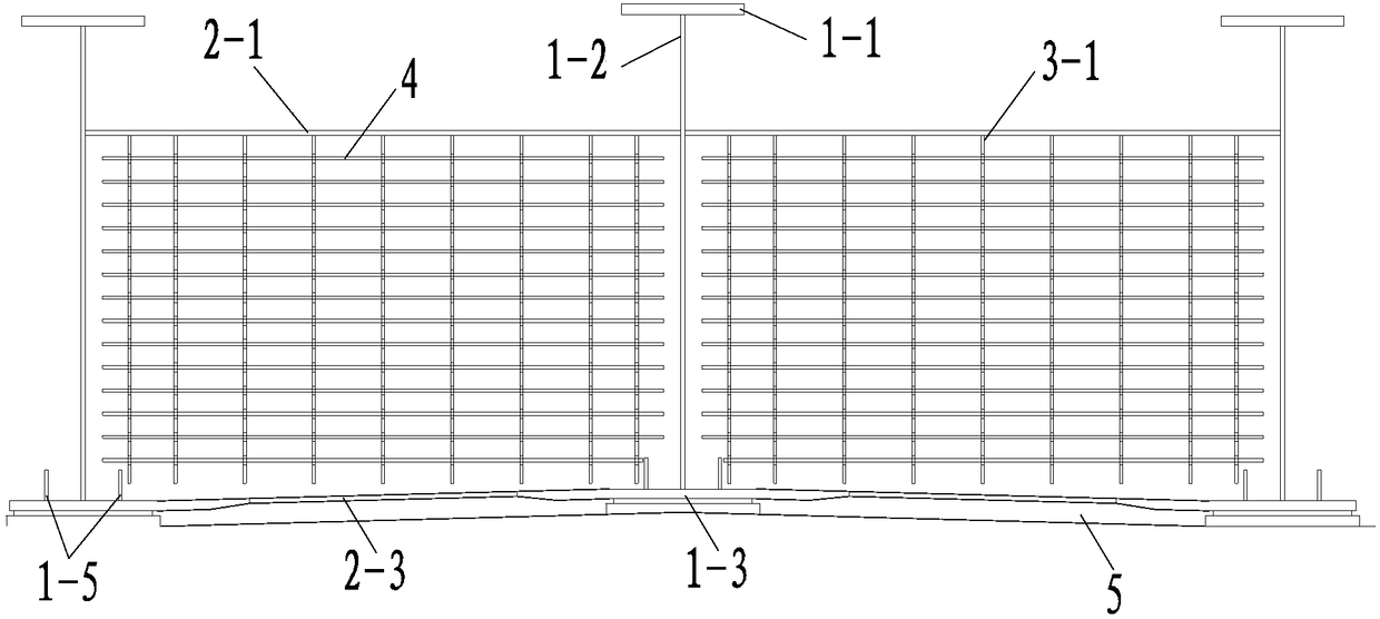
[0029] Such as Figure 1 ~ Figure 3 As shown, the composite steel plate girder bridge pier girder solid structure of the present invention includes an I-shaped steel girder and a beam arranged between the steel girders. The steel girder includes an upper flange plate 1-1, a web 1-2, Lower flange plate 1-3, transverse stiffener plate 1-4, longitudinal stiffener plate 1-5; beam includes upper flange plate 2-1, web plate 2-2, lower flange plate 2-3; passed value According to the analysis, the contact between the lower flange plate 1-3 of the main girder and the outer edge of the pier bears a relatively large local pressure. The lower flange plate 1-3 is equipped with longitudinal stiffening ribs 1-5; the inner sides of the main girder web 1-2 and the beam w...


PUM


Abstract

The invention discloses a combined rigid frame steel plate girder-pier girder solid structure. According to the structure, an I-shaped steel main girder and a crossbeam form a box-shaped grid room, perforated plate connection pieces are arranged inside web plates of the box-shaped grid room and penetrate through reinforcing bars and pour concrete, so as to solidify the pier girder. To ensure thatthe load born by the main girder is transmitted to the pier effectively, perforated plate connection pieces are arranged inside web plats of the steel main girder and the crossbeam of the box-shaped grid room, the perforated plates penetrate through common reinforcing bars and then concrete is cast so as to resist shear force, shaft force and bending moment of the pier girder solidified part; thesteel plate girder and the concrete pier are connected through the perforated plates, so that the structure is simple, bears forces reasonably and transmits force reliably, can meet various requirements of normal use and limit loading, improves the crossover capability of the bridge while the dead weight is reduced, is convenient and quick in construction, and solves main problems that the web plate concrete cracks, the middle span warps downwards and the anti-seismic performance is reduced in the existing concrete rigid frame bridge due to long-term load.

Description

technical field [0001] The invention belongs to the technical field of bridge engineering, and in particular relates to a pier-beam solid structure of a combined rigid steel plate girder bridge. Background technique [0002] With the rapid development of my country's economy, the use requirements and technical standards of bridge construction continue to increase, and the design concept of bridges pays more attention to the driving comfort, durability, and construction convenience of bridges. Rigid frame bridges have the advantages of large clearance under the bridge, saving supports, beautiful appearance, good bridge deck smoothness and high seismic performance, and are excellent bridge structures suitable for crossing deep and wide river valleys. After the pier-beam is consolidated in the rigid frame bridge, under the action of vertical load, the end of the main girder will generate a negative bending moment, thereby reducing the positive bending moment at the mid-span, an...

Claims


Application Information

Patent Timeline
IPC IPC(8): E01D19/00E01D19/02
CPCE01D19/00E01D19/02
Inventor 余茂峰郭斌强茅兆祥叶建龙刘玉擎王贤林
Owner ZHEJIANG PROVINCIAL INST OF COMM PLANNING DESIGN & RES CO LTD
Why Eureka
Eureka Blog
Learn More