
Low-loss high-speed cable and flat cable

A low-loss, high-speed technology, used in cables, insulated cables, communication cables, etc., can solve the problems of low dielectric constant consistency, large signal attenuation loss, poor high temperature resistance, etc., to ensure stable and effective transmission, The effect of reducing signal attenuation loss and high dielectric constant consistency

Pending Publication Date: 2018-08-07
深圳讯诺科技有限公司
View PDF0 Cites 7 Cited by
  • Summary
  • Abstract
  • Description
  • Claims
  • Application Information

AI Technical Summary

Problems solved by technology

[0003] However, the current SFP, QSFP, CXP, SAS and other interface cables still have the following problems: first, the insulating material of the core group is usually PE, the wire is relatively hard, and the high temperature resistance is not good; second, the shielding layer is difficult to align the core The group conducts 360-degree signal shielding without dead ends. In the future high-frequency, high-power signal transmission process, the stability and effective transmission of the signal cannot be guaranteed; third, the core group is two core wires that are extruded separately Combination, the consistency of the core wires needs to be matched between the two core wires, the inconsistency of capacitance and impedance will lead to signal distortion, the consistency of the dielectric constant is relatively low, and the signal attenuation loss is large

Method used


Image

  • Low-loss high-speed cable and flat cable
  • Low-loss high-speed cable and flat cable
  • Low-loss high-speed cable and flat cable

Examples


Embodiment 1

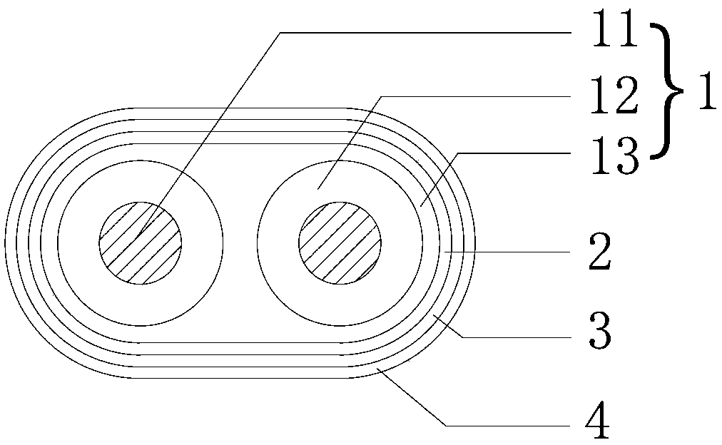
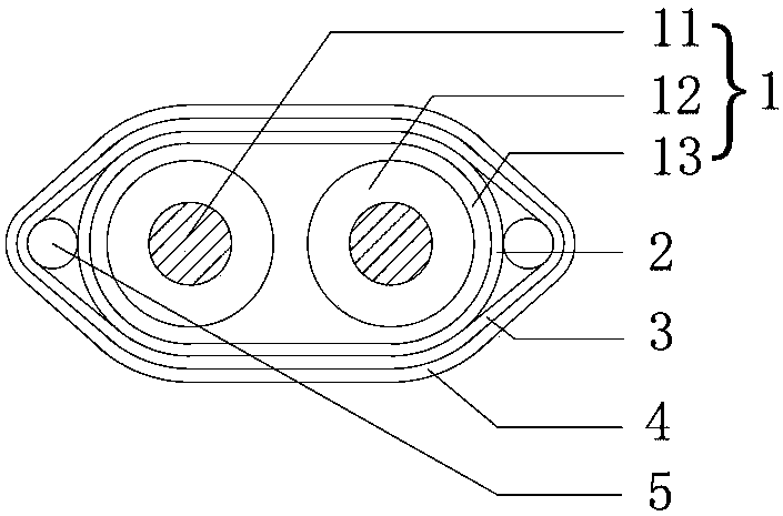
[0023] Such as figure 1 and figure 2 As shown, a low-loss high-speed cable includes a core group 1, a first shielding layer 2, a second shielding layer 3 and an outer coating layer 4; the first shielding layer 2 is wrapped outside the core group 1 , the second shielding layer 3 is wrapped outside the first shielding layer 2, and the outer layer 4 is wrapped outside the second shielding layer 3; the core set 1 includes two inner conductors 11, two The inner conductor 11 is covered with a first perfluoroethylene propylene copolymer insulating layer 12 separately, and the two first perfluoroethylene propylene copolymer insulating layers 12 are covered with a second perfluoroethylene propylene copolymer extruded at the same time. The physical insulating layer 13, the cross-sectional shape of the second perfluoroethylene propylene copolymer insulating layer 13 is racetrack-shaped.

[0024] Such as figure 1 and figure 2 As shown, the first shielding layer 2 is a copper foil la...

Embodiment 2

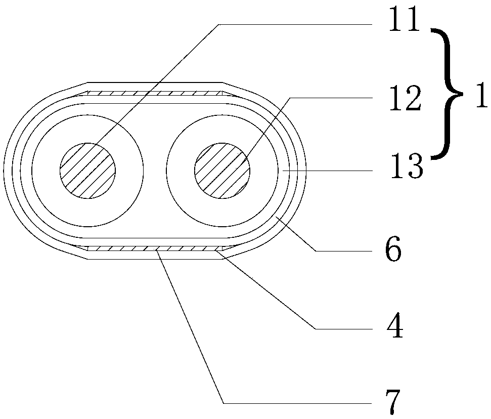
[0028] Such as image 3 As shown, a low-loss high-speed cable includes a core group 1, a shielding layer 6 and an outer coating layer 4; the shielding layer 6 is covered outside the core group 1, and the outer coating layer 4 is coated on the Outside the shielding layer 6; the core group 1 includes two inner conductors 11, and the two inner conductors 11 are separately covered with a first perfluoroethylene propylene copolymer insulating layer 12, and the two first perfluoroethylene propylene copolymers The outside of the material insulating layer 12 is covered with a second perfluoroethylene propylene copolymer insulating layer 13 extruded simultaneously, and the cross-sectional shape of the second perfluoroethylene propylene copolymer insulating layer 13 is racetrack-shaped; the shielding layer 6 and the outer Two flat ground wires 7 are sandwiched between the layers 4 , and the two flat ground wires 7 are located on the upper and lower sides of the shielding layer 6 .

[0...

Embodiment 3

[0031] Such as Figure 4 As shown, a low-loss high-speed flat cable is composed of at least two groups of low-loss high-speed cables arranged in the first technical solution above, and each low-loss high-speed cable is also covered with a second thermal insulation layer. Melt PET tape layer8. The low-loss high-speed cables are horizontally connected in a row through the second hot-melt PET tape layer 8 .


PUM

PropertyMeasurementUnit
Thicknessaaaaaaaaaa
Diameteraaaaaaaaaa
Thicknessaaaaaaaaaa

Abstract

The invention discloses a low-loss high-speed cable and a flat cable. The low-loss high-speed cable comprises a wire core group, a first shielding layer, a second shielding layer and an outer coatinglayer; the first shielding layer wraps the wire core group; the second shielding layer wraps the first shielding layer; and the outer coating layer coats the second shielding layer; the wire core group comprises two inner conductors; two first fluorinated ethylene propylene insulating layers respectively cover the two inner conductors; and the two first fluorinated ethylene propylene insulating layers are covered with a second fluorinated ethylene propylene insulating layer which is formed by simultaneous extrusion molding. The wire rod of the low-loss high-speed cable of the invention is soft; the low-loss high-speed cable has high temperature resistance; the shielding layers of the low-loss high-speed cable can achieve full shielding; and the dielectric constant consistency of the low-loss high-speed cable is relatively high. With the low-loss high-speed cable adopted, signal attenuation loss can be reduced.

Description

technical field [0001] The invention relates to the technical field of communication wires, in particular to a low-loss high-speed cable and a flat cable. Background technique [0002] At present, electronic signal interface lines such as SFP, QSFP, CXP, and SAS are gradually being applied in communication equipment. SFP (Small Form-factor Pluggables) can be simply understood as an upgraded version of GBIC; the SFP module (half the size of the GBIC module, can configure more than double the number of ports on the same panel; because the SFP module is functionally different from The GBIC is basically the same, therefore, it is also called miniaturized GBIC (Mini-GBIC) by some switch manufacturers; the SFP module compresses the size and power consumption by placing the CDR and electrical dispersion compensation outside the module; it is used for telecommunications and Optical communication applications in data communication; SFP connects network equipment such as switches, ro...

Claims


Application Information

Patent Timeline
IPC IPC(8): H01B7/02H01B7/04H01B7/08H01B7/17H01B7/29H01B11/00
CPCH01B7/0216H01B7/0275H01B7/04H01B7/0807H01B7/0861H01B7/17H01B7/292H01B11/002
Inventor 李军孔浩于国庆付善波贾利宾
Owner 深圳讯诺科技有限公司
Learn More