Fuse carrying device

A technology of bearing devices and fuses, applied in emergency protection devices, electrical components, circuits, etc., can solve the problems of unsatisfactory contact conduction effect, high material cost and processing cost, complex structure and process, etc., to save production costs , good electrical conductivity and good mechanical properties

Pending Publication Date: 2018-08-07
天立电机(宁波)有限公司
View PDF1 Cites 5 Cited by
  • Summary
  • Abstract
  • Description
  • Claims
  • Application Information

AI Technical Summary

Problems solved by technology

At present, the contact conduction effect of such products on the market is not very ideal. The disadvantages of the contact pieces of the two types of fuses on the market are as follows:
[0004] Type 1: The metal clip is made of high-strength materials such as tin phosphor bronze, which can withstand repeated insertion and removal of fuses, but the material cost of the product is high and the conductivity is poor
[0005] Type 2: The metal clip is made of medium-strength, high-conductivity materials such as brass, and the cost of raw materials is relatively low. However, due to poor structure, the contact piece is prone to plastic deformation after repeated plugging and unplugging, resulting in poor contact.
[0006] Type 3: Use brass, a raw material with better conductivity and lower cost, but in order to improve the elasticity and strength weaknesses of the brass material, a more complicated sheet metal bending structure is designed, so that although the conductivity and elasticity are better , but due to the complex structure and process, the material cost and processing cost are relatively high

Method used


Image

  • Fuse carrying device
  • Fuse carrying device
  • Fuse carrying device

Examples


Embodiment Construction

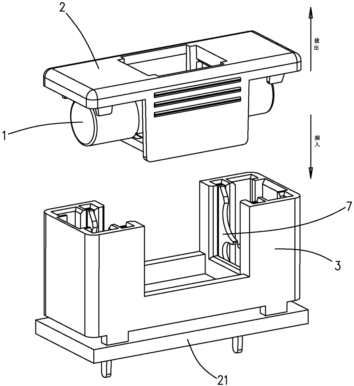
[0030] as follows Figure 1 to Figure 10 The preferred embodiment of the fuse carrying device of the present invention is shown as an example to illustrate the specific implementation of the present invention.

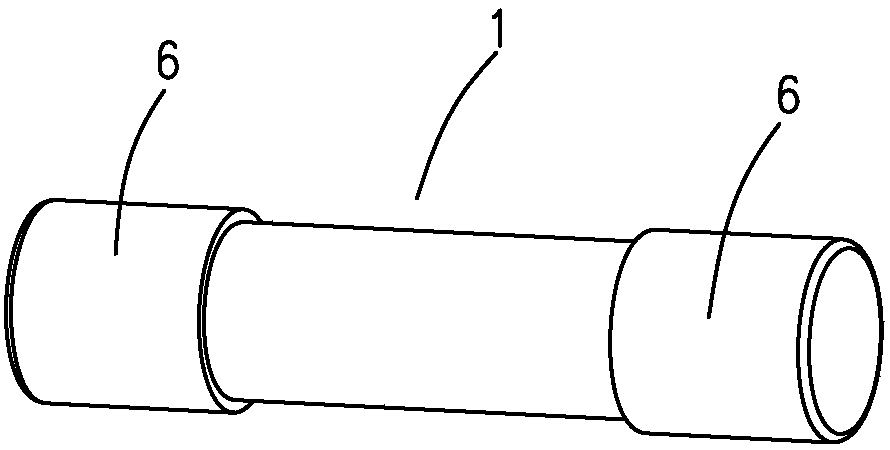
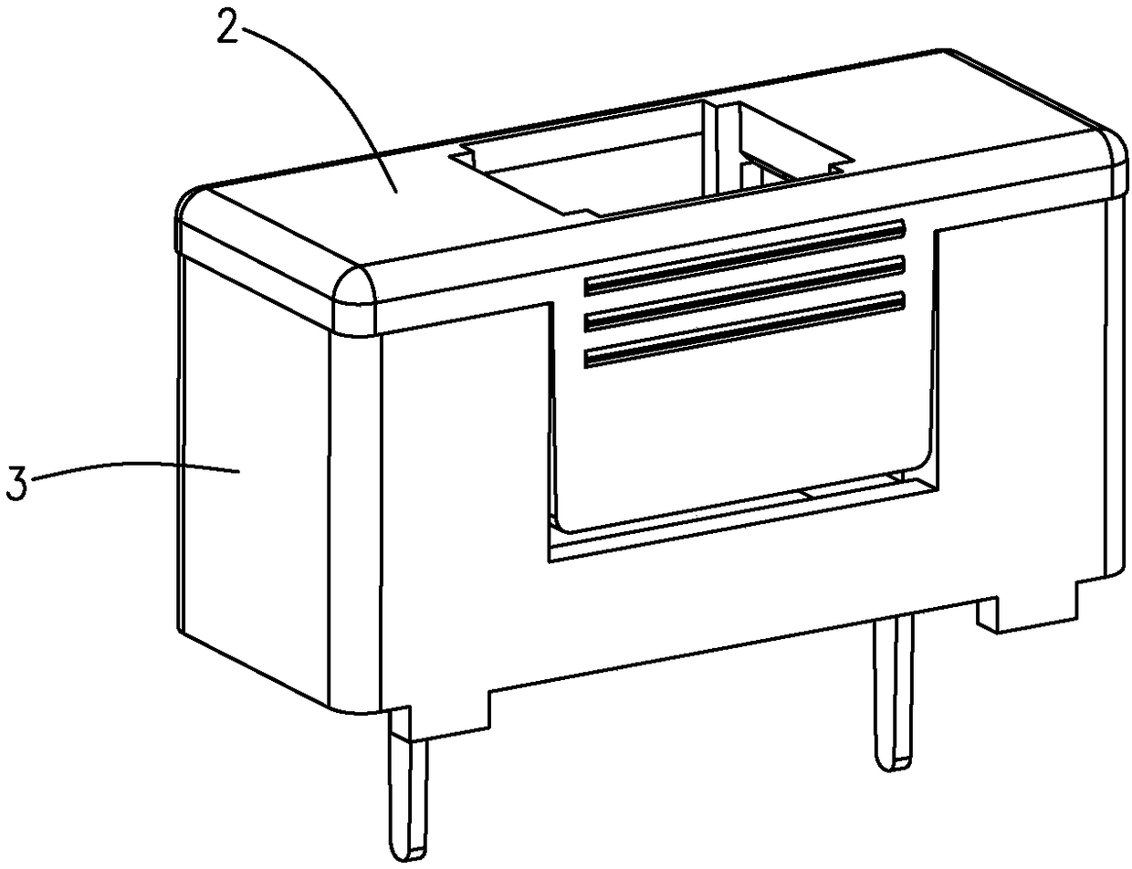
[0031] The fuse carrying device of the present invention such as Figure 2 to Figure 4 shown, including the figure 1 The carrier (2) of the cylindrical standard fuse (1) shown is for the carrier (2) to be inserted into the fixed seat (3) that is pulled out, and the carrier (2) and the fixed seat (3) are both Made of insulating material; the carrier (2) includes a cover (4) and a carrier (5) extending downward from the cover (4); the fuse carrying device also includes two pieces arranged at intervals The contact piece (7) made of conductive metal is used to clamp the columnar conductive metal contact caps (6) at both ends of the fuse (1), and the contact piece (7) is in contact with the fuse (1) to be contacted. The axes are set perpendicular to each other. Such as ...


PUM


Abstract

The invention provides a fuse carrying device. The fuse carrying device comprises a carrying body (2) and a fixing seat (3), wherein the carrying body (2) comprises a cover plate (4) and a carrying frame (5); and the fuse carrying device further comprises two contact sheets (7); contact clamping openings (8) are formed in the contact sheets (7); the contact clamping opening is an incomplete circular notch having an upwards-facing opening (9); when a fuse (1) is inserted into the contact sheets (7), the contact clamping openings (8) are expanded, the contact cap (6) of the fuse (1) is clamped,so that the fuse (1) can conductively contact with the contact sheets (7); the lower parts of the contact sheets (7) are provided with pins (10) for external electrical connection; longitudinal grooves (11) for accommodating the contact sheets (7) are formed in the fixing seat (3) at intervals; inside-groove notches (12) are formed in the longitudinal grooves (11); and the pins (10) pass through the inside-groove notches (12). The force bearing structures of the contact sheets are optimized, so that the contact sheets still maintain good elasticity after plugging and pulling out are performeda plurality of times with the advantages of a brass material kept, and therefore, the stability of electrical contact can be ensured.

Description

technical field [0001] The invention relates to a fuse carrying device. Background technique [0002] A fuse is an electrical appliance that fuses the fuse with the heat generated by itself and disconnects the circuit when the current exceeds the specified value. The fuse is based on the fact that after the current exceeds the specified value for a period of time, the heat generated by itself melts the melt, thereby disconnecting the circuit; a current protector made by using this principle. Fuses are widely used in high and low voltage power distribution systems and control systems, as well as electrical equipment. As short circuit and overcurrent protectors, fuses are one of the most commonly used protection devices. Common fuses are cylindrical standard fuses with cylindrical conductive metal contact caps at both ends, such as figure 1 shown. [0003] The specific structural schemes of the fuse carrying device are different. The connection between the two poles of the...

Claims


Application Information

Patent Timeline
Patent Type & Authority Applications(China)
IPC IPC(8): H01H85/20H01H85/22
CPCH01H85/22H01H85/202
Inventor 王舸姚海振
Owner 天立电机(宁波)有限公司
Why Eureka
Try Eureka