
Fan variable-pitch sliding ring

A fan and slip ring technology, applied in wind turbines, wind turbine control, motors, etc., can solve the problems of signal attenuation, excessive fluctuation of internal resistance resistance, short service life, etc., to improve reliability and solve impedance matching. , the effect of improving life expectancy

Pending Publication Date: 2018-08-07
SUZHOU ENBIJI PRECISION ELECTRIC CO LTD
View PDF1 Cites 2 Cited by
  • Summary
  • Abstract
  • Description
  • Claims
  • Application Information

AI Technical Summary

Problems solved by technology

The following problems exist in the process of use: 1. The brush wire and the conductive slideway are in a dynamic contact state during the rotation of the traditional pitch slip ring. The gold brush and gold-plated material are soft and not wear-resistant. If there is no maintenance, the slip ring will The road and the gold brush are quickly worn out, generating dust, and the internal resistance fluctuates too much, which will affect the impedance matching and signal attenuation to varying degrees; 2. The dynamic contact between the conductive ring and the brush wire will cause background noise. The problem of stability and excessive size, when high-speed signals are passed, it is inevitable to cause the reflection of the waveform to form the ringing phenomenon of the signal. The existing method can only reduce the transmission rate of the control signal to control the signal data error rate; 3. The vibration environment of the wind turbine cabin is very harsh, and it is easy to cause loose contact between the brush wire and the conductive ring
[0005] Although the device can realize signal transmission, it is still a contact connection, and there are still problems such as short service life, affecting impedance matching, signal attenuation, and signal reflection.

Method used


Image

  • Fan variable-pitch sliding ring
  • Fan variable-pitch sliding ring
  • Fan variable-pitch sliding ring

Examples


Embodiment Construction

[0023] The preferred embodiments of the present invention will be described in detail below in conjunction with the accompanying drawings, so that the advantages and features of the present invention can be more easily understood by those skilled in the art, so as to define the protection scope of the present invention more clearly.

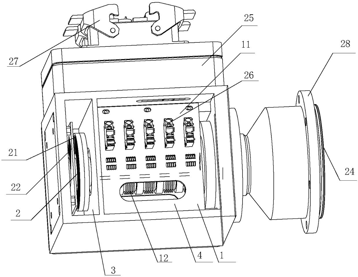
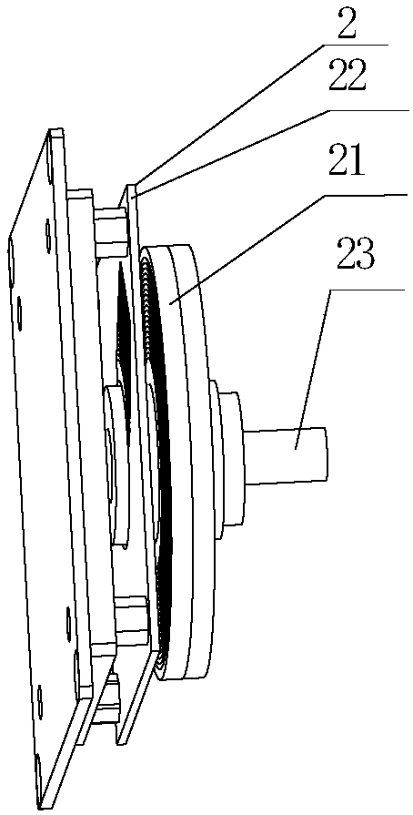
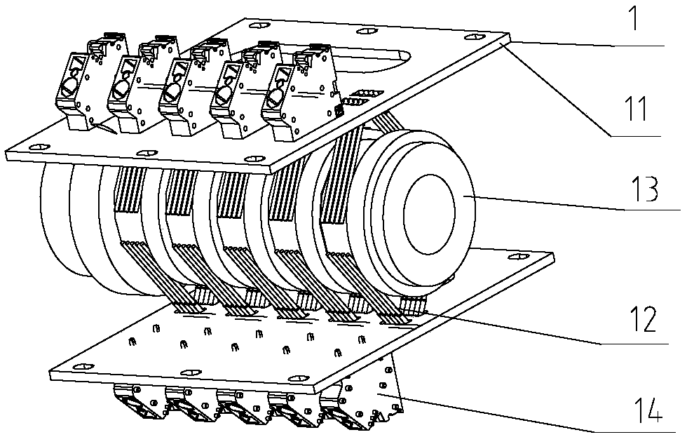
[0024] See attached Figure 1-Figure 7 As shown, a fan pitch slip ring in this embodiment includes a stator connected to the pitch control cabinet of the fan, a rotor connected to the pitch controller of the fan and matched with the stator, and the rotor includes a The power slide unit 1 and the non-contact transmission slide unit 2 for transmitting signals. In this embodiment, in order to reduce the space volume and facilitate transportation and installation, a housing is provided outside the stator and rotor, and the housing is divided into a non-contact signal cavity 3 and a power signal cavity 4 by a partition with holes. The non-contact sig...


PUM


Abstract

The invention discloses a fan variable-pitch sliding ring. The fan variable-pitch sliding ring comprises a stator connected with a variable-pitch control cabinet of a fan, and a rotor connected with avariable-pitch device of the fan and matched with the stator, wherein the rotor comprises a power slideway unit for transmitting power and a noncontact transmission slideway unit for transmitting a signal. By adopting the independent noncontact transmission slideway unit, the problems that the service life is short, the impedance matching is influenced, the signal is attenuated, and the signal isreflected can be solved.

Description

technical field [0001] The invention relates to the technical field of wind power generation equipment, in particular to a wind turbine pitch slip ring. Background technique [0002] The pitch slip ring of the wind turbine is responsible for communicating with the rotating body and transmitting the electrical control signal of the signal. The pitch slip ring is usually installed at the end of the low-speed shaft of the gearbox. It is mainly composed of two parts: the rotating part and the stationary part, which transmit the power supply, control signals and communication signals to the pitch control system. In the safety and stability performance of the pitch control system, the fan pitch slip ring plays a vital role. [0003] The communication slideway of the current wind turbine pitch slip ring mainly uses a sliding electrical contact device matched with a conductive ring and a brush wire for signal transmission. The following problems exist in the process of use: 1. The...

Claims


Application Information

Patent Timeline
Patent Type & Authority Applications(China)
IPC IPC(8): H02K11/35F03D7/02
CPCF03D7/02H02K11/35Y02E10/72
Inventor 严丰仲济祥朱鹏
Owner SUZHOU ENBIJI PRECISION ELECTRIC CO LTD
Learn More