Supercharge Your Innovation With Domain-Expert AI Agents!

Efficient machining center machine

A machining center and high-efficiency technology, applied in metal processing machinery parts, metal processing, metal processing equipment, etc., can solve the problems of the need to improve the processing accuracy, the low equipment utilization rate, and the machining accuracy deviation, and achieve high equipment utilization and equipment. Low cost and smooth operation

Pending Publication Date: 2018-08-10
DONGGUAN JIR FINE MACHINERY
View PDF0 Cites 2 Cited by
  • Summary
  • Abstract
  • Description
  • Claims
  • Application Information

AI Technical Summary

Problems solved by technology

[0003] For the processing of polyhedral parts, different processing equipment is usually used to process one surface first, and then process the other surfaces. On the one hand, the workpiece is clamped multiple times, and the work efficiency is low. Deviation, the second aspect, requires the use of multiple machining centers, low equipment utilization and high equipment costs
In the third aspect, during the machining process, due to the high-speed rotation of the machining spindle and the discontinuity of tool cutting, the entire machining part is easy to shake, and the machining accuracy needs to be improved.

Method used


Image

  • Efficient machining center machine
  • Efficient machining center machine
  • Efficient machining center machine

Examples


Embodiment Construction

[0034] The present invention will be further described below in conjunction with the accompanying drawings.

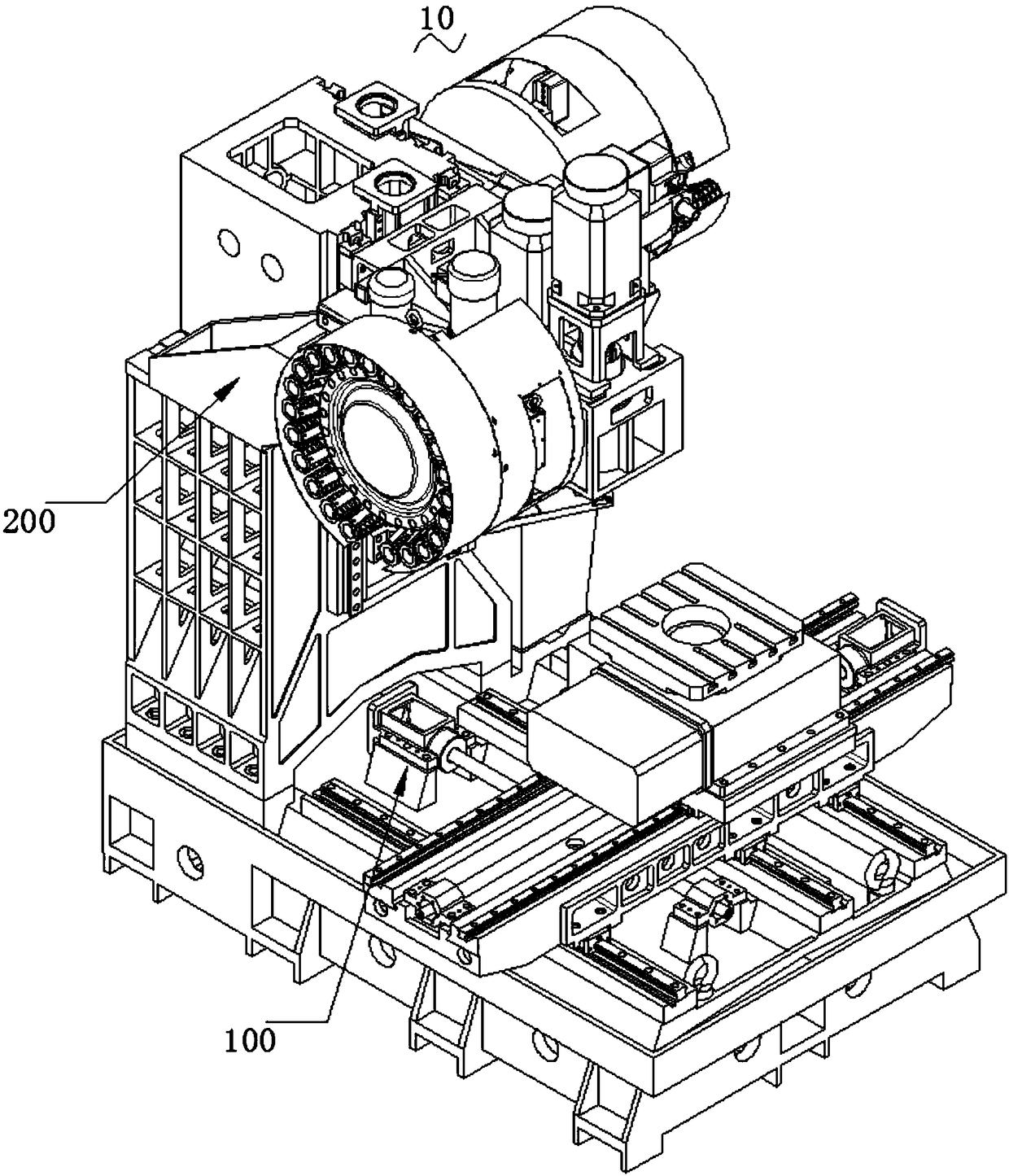
[0035] Such as Figure 1 ~ Figure 2 Shown are respectively perspective views of different viewing angles of the present invention.

[0036] The high-efficiency machining center 10 includes a workbench 100 and a processing part 200 located at one end of the workbench 100 .

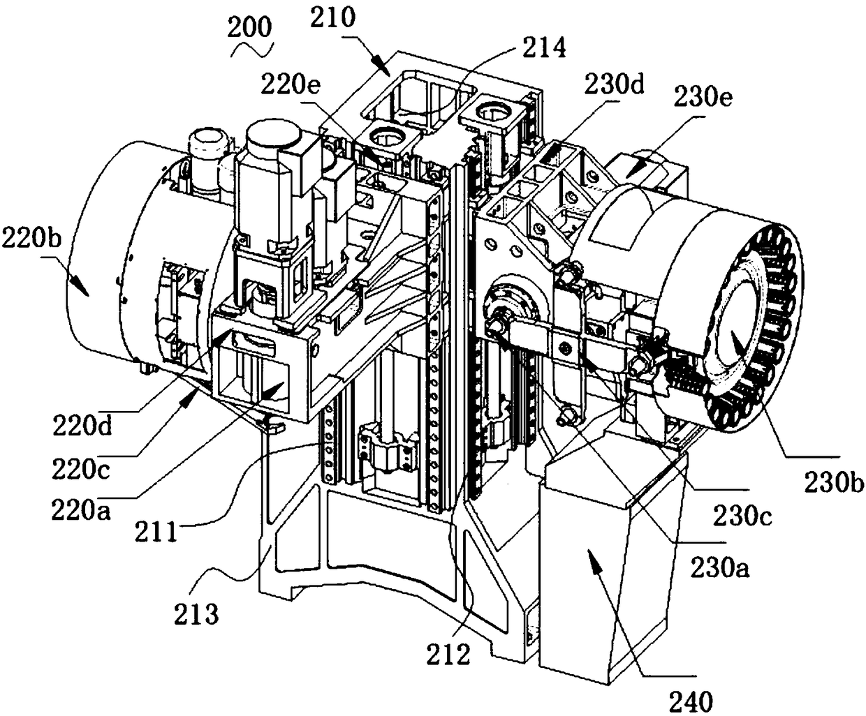
[0037] Such as Figure 3 ~ Figure 5 Shown are perspective views and front views of the processing part of the present invention at different angles of view.

[0038] The processing part 200 includes a square column 210, a first processing machine head 220a and a first tool magazine 220b slidingly arranged on one side of the square column 210, and a first tool magazine 220b connected to the first processing machine head 220a and the first tool magazine 220b. The knife arm 220c is slidably arranged on one side of the square column 210 and is located on the second processing head 230a and the second...


PUM


Abstract

The invention relates to the field of machining center machines, in particular to an efficient machining center machine. The efficient machining center machine comprises a workbench and a machining part located on the end portion of one side of the workbench; the machining part comprises a square stand column, a first machining machine head, a first tool changer, a first tool changing arm connected between the first machining machine head and the first tool changer, a second machining machine head, a second tool changer and a second tool changing arm connected between the second machining machine head and the second tool changer, wherein the first machining machine head and the first tool changer are arranged on one side of the square stand column in a sliding manner; the second machiningmachine head and the second tool changer are arranged on one side of the square stand column in a sliding manner and located on the adjacent side faces of the first machining machine head; the first machining machine head vertically faces the horizontal plane, and the second machining machine head is parallel with the horizontal plane; and the first machining machine head and the second machiningmachine head are both located above the workbench. The efficient machining center machine is high in integration degree, high in work efficiency, equipment utilizing rate and machining precision and low in equipment cost.

Description

technical field [0001] The invention relates to the field of machining centers, in particular to high-efficiency machining centers. Background technique [0002] Metal processing machines are metal processing machine tools, also called CNC machine tools, referred to as machining centers (the English name is Computerized Numerica1 Contro1 Machine referred to as cnc). Metal processing center is a high-efficiency automatic machine tool suitable for processing complex-shaped workpieces, which is usually composed of control system, servo system, detection system, mechanical transmission system and other auxiliary systems. [0003] For the processing of polyhedral parts, different processing equipment is usually used to process one surface first, and then process other surfaces. Deviation, the second aspect, requires the use of multiple machining centers, low equipment utilization and high equipment costs. Thirdly, during the machining process, due to the high-speed rotation of ...

Claims


Application Information

Patent Timeline
IPC IPC(8): B23Q1/01B23Q1/58B23Q1/62B23Q3/155B23Q15/22B23Q39/00
CPCB23Q1/015B23Q1/585B23Q1/621B23Q3/1554B23Q15/22B23Q39/00B23Q2039/006
Inventor 胡真清
Owner DONGGUAN JIR FINE MACHINERY
Features
  • R&D
  • Intellectual Property
  • Life Sciences
  • Materials
  • Tech Scout
  • Unparalleled Data Quality
  • Higher Quality Content
  • 60% Fewer Hallucinations
Learn More