An energy-dissipating shear wall with limbs

A shear wall and connecting limb technology, applied in the direction of wall, building, building type, etc., can solve the problems of complex on-site construction, no structural system, uneconomical, etc. The effect of structural design freedom

Active Publication Date: 2019-07-26
NANTONG LANKE DAMPING TECH CO LTD
View PDF5 Cites 0 Cited by
  • Summary
  • Abstract
  • Description
  • Claims
  • Application Information

AI Technical Summary

Problems solved by technology

[0004] Although the steel-concrete composite structural system currently used in high-rise buildings can achieve relatively large lateral stiffness relatively economically, on the one hand, its performance and damage mechanism are complex, which is not conducive to designers' grasp, and it is difficult to form damage controllable and earthquake recoverable concept of architecture
At present, there are some reports on the application of some energy-dissipating and shock-absorbing products to the steel-concrete composite structure system, but generally by replacing a small amount of concrete coupling beams in the original structure, replacing a small amount of ordinary supports with buckling restraint supports, or adding a small amount of viscous dampers The design scheme, but did not form a proprietary structural system
Moreover, most of the existing energy dissipation and shock absorption products applied to steel-concrete composite structures are rigid connection frames. Although the rigid connection frame can provide greater redundancy for the structure, the rigid connection frame leads to complex on-site construction, and the construction cost and The time is greatly increased; while the metal energy dissipation and shock absorption products have very good fatigue performance and ductility, the excessive redundancy of the frame structure leads to the performance of the metal energy dissipation and shock absorption products not being fully utilized, and the structural design is too conservative and Uneconomical

Method used


Image

  • An energy-dissipating shear wall with limbs
  • An energy-dissipating shear wall with limbs
  • An energy-dissipating shear wall with limbs

Examples


Embodiment 1

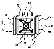
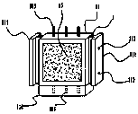
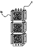
[0039] Such as Figure 5 As shown, a kind of energy dissipation shear wall with limbs is mainly composed of prefabricated shear wall panels 1, spiral double-step connecting beams 2 and steel frame connecting columns 3, such as figure 1 , 2 As shown, the prefabricated shear wall panel 1 includes a shear wall panel frame 11, a first web 12, a second web 13, a protective anti-shock component 14 and high-strength anti-shock concrete 15, and the left side of the shear wall panel frame 11 The rib and the right side rib are respectively provided with T-shaped ribs 111, and the T-shaped ribs 111 are positioned at the outer direction of the left side rib and the right side rib and are equal in length to the left side rib and the right side rib, and the vertical section of the T-shaped rib 111 There are several transverse through-holes 112 on the top, and three steel bar heads 113 are arranged on the upper edge of the shear wall panel frame 11. The steel bar heads 113 are perpendicular...

Embodiment 2

[0053] The difference with Example 1 is:

[0054] (1) if Figure 6a , 6b , 7a, and 7b, the steel frame connecting column 3 is a double T horizontal groove structure and a double T corner groove structure, which is used to connect such as Figure 12b , 12d , and 12e show two adjacent and at the same level and two adjacent and mutually perpendicular shear wall pier units 1a in the shape of a square, a concave, and a zigzag.

[0055] (2) The composition of high-strength impact-resistant concrete 15 includes by weight percentage: 27% sand and gravel, 18% cement powder, 7.5% silicon PU balls, 5.5% corundum powder, 3% explosion-proof clay, and 1.5% tempered glass beads , 0.5% binder, 0.3% dispersant, 1.5% asbestos mesh fiber, 1.5% high polyethylene fiber, 3.5% slag, 2% furnace ash, and the balance is water; among them, silicon PU balls have excellent elasticity, Added in concrete, it can make the concrete have a certain limit of self-buffering ability; the explosion-proof mortar...

Embodiment 3

[0057] The difference with Example 1 is:

[0058] (1) if Figure 6a , 6b , 6c, 7a, 7b, and 7c, the steel frame connecting column 3 is a double T horizontal groove structure, a double T corner groove structure and a triple T vertical groove structure, which are used to connect such as Figure 12c , 12f Shown are two adjacent and at the same level, two adjacent and perpendicular to each other, and three adjacent U-shaped and E-shaped shear wall pier units 1a arranged in a T-shape.

[0059] (2) The composition of high-strength impact-resistant concrete 15 includes, by weight percentage: 30% sand and gravel, 20% cement powder, 8% silicon PU balls, 6% corundum powder, 4% explosion-proof clay, and 2% tempered glass beads , 1% binder, 0.5% dispersant, 2% asbestos mesh fiber, 2% high polyethylene fiber, 4% slag, 3% furnace ash, and the balance is water; among them, silicon PU balls have excellent elasticity, Added in concrete, it can make the concrete have a certain limit of self-...


PUM


Abstract

The invention discloses an energy dissipation coupled shear wall and belongs to the technical field of building structures. The energy dissipation coupled shear wall is mainly composed of prefabricated shear wall boards, spiral double-order coupling beams and steel rib connecting columns, wherein upper and lower adjacent prefabricated shear wall boards are self-coupled to form shear wall limb units, the shear wall limb units are connected through the steel rib connecting columns to form shear wall limbs, and the shear wall limbs are connected through the steel rib connecting columns to form the energy dissipation coupled shear wall; each prefabricated shear wall board comprises a shear wall board frame, a first web plate, a second web plate, a protective anti-impact assembly and high-strength anti-impact concrete; each spiral double-order coupling beam comprises a first spiral arm, a second spiral arm, a connecting short limb, a first connector, a second connector and an elastic protective drum; and each steel rib connecting column comprises a double-T horizontal type groove structure, a double-T corner type groove structure and a three-T vertical type groove structure. In conclusion, the energy dissipation coupled shear wall disclosed by the invention is free in structural design and high in impact resistance.

Description

technical field [0001] The invention belongs to the technical field of building structures, and in particular relates to an energy-dissipating shear wall with limbs. Background technique [0002] Most of the reinforced concrete (RC) high-rise buildings in my country adopt the shear wall structure system, the frame-shear wall structure system, and the frame-core tube structure system. The core tube composed of the combined limb wall often bears most of the base shear force and most of the earthquake overturning bending moment of the high-rise building structure. At present, the most widely used is still the RC joint wall. Under the reciprocating action of the earthquake, the RC coupling beam first yields to dissipate the seismic energy, and the bottom of the rear wall yields to form a plastic hinge. During the Wenchuan earthquake in 2008, the combined limb wall designed in GB50011-2001 "Code for Seismic Design of Buildings" showed good seismic performance, and there were also...

Claims


Application Information

Patent Timeline
Patent Type & Authority Patents(China)
IPC IPC(8): E04B2/56E04B1/98E04H9/02
CPCE04B2/56E04H9/021
Inventor 李国强宫海胡大柱尹文汉孙飞飞
Owner NANTONG LANKE DAMPING TECH CO LTD
Why Eureka
Try Eureka