
Audio optical fiber support

An optical fiber support and audio technology, which is applied to electrical components, electric solid devices, circuits, etc., can solve the problems of small number of single supports, low actual production capacity, and insufficient flatness of four pins.

Pending Publication Date: 2018-08-10
深圳市燚磊实业有限公司
View PDF0 Cites 0 Cited by
  • Summary
  • Abstract
  • Description
  • Claims
  • Application Information

AI Technical Summary

Problems solved by technology

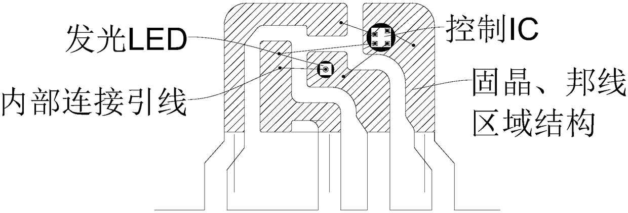
[0004] 1) Due to the long pin extension and no auxiliary support structure in the top side of the bracket for die bonding and wire bonding, the flatness of the four pins is not enough, which reduces the yield of die bonding and wire bonding
[0005] 2) The number of single brackets is small, the production equipment has a long waiting time for refueling, and the actual production capacity is low;
[0006] 3) There is no anti-fooling protective colloid in the die-bonding and bonded wire areas of the body bracket. During the processing, it is easy to be collided or broken by external factors after bonding the gold wires and reduce the yield rate;
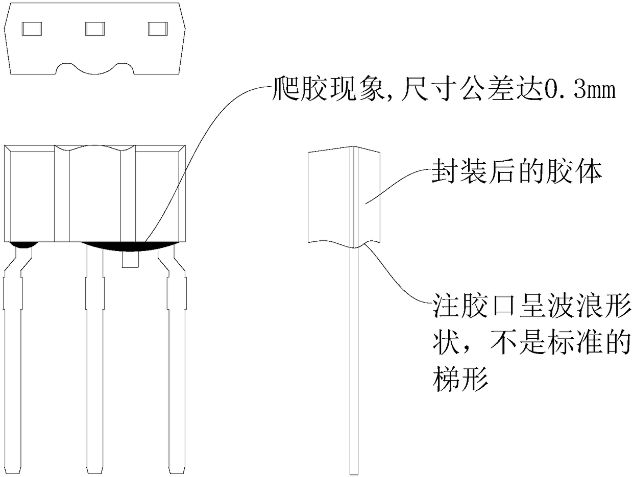
[0007] 4) Potting and forming: it is completed by combining the packaging mold strip and the bracket (first fill the mold cup with epoxy resin glue, then insert the bracket into the mold strip, put it in the oven to bake and dry to form, because the single strip The weight of the bracket is too light, and the mold strips are heated and deformed during the baking process, which may cause the bracket to float up and cause poor insertion;
[0009] 6) The formed colloid is transparent, and there is no medium on the back of the red LED to reflect light, which seriously reduces the luminance of the LED

Method used


Image

  • Audio optical fiber support
  • Audio optical fiber support
  • Audio optical fiber support

Examples


Embodiment Construction

[0033] In order to make the objectives, technical solutions, and advantages of the embodiments of the present invention clearer, the technical solutions in the embodiments of the present invention will be described clearly and completely in conjunction with the accompanying drawings in the embodiments of the present invention. Obviously, the described embodiments It is a part of the embodiments of the present invention, not all the embodiments. The components of the embodiments of the present invention generally described and illustrated in the drawings herein may be arranged and designed in various different configurations. Therefore, the following detailed description of the embodiments of the present invention provided in the accompanying drawings is not intended to limit the scope of the claimed invention, but merely represents selected embodiments of the present invention. Based on the embodiments of the present invention, all other embodiments obtained by those of ordinar...


PUM

PropertyMeasurementUnit
Thicknessaaaaaaaaaa

Abstract

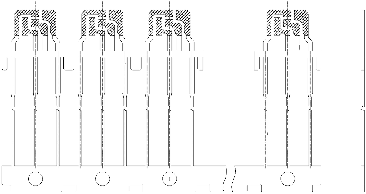
The invention provides an audio optical fiber support, and relates to the technical field of optical fiber supports. The audio optical fiber support comprises a support assembly, and fixed wafers andbonding wires are machined on the support assembly. The support assembly is composed of 80 support bodies, and each support body is integrated with a colloid through four supports, so that the supportbody forms a concave cavity; the fixed wafers are arranged on the tops of the side faces of the supports, and each fixed wafer comprises a fixed control IC and a red light LED; wires are arranged onthe fixed control ICs and the red light LEDs respectively; the bonding wires are arranged on the tops of the side faces of the supports, and the height of the colloid walls of the colloids are largerthan the height of the fixed wafers and the bonding wires. Four existing supports are integrated, a white PPA material is used, and the colloids and the supports are integrated through injection molding, so that the support bodies are provided with the concave cavities and have standard appearance; an inclined PPA white glue wall is relatively high in light reflection and refractivity, the brightness is enhanced, and the flatness in the fixed wafer and the binding wire area is good.

Description

Technical field [0001] The present invention relates to the technical field of optical fiber brackets, and in particular to an audio optical fiber bracket. Background technique [0002] The audio optical fiber support in the prior art is a flat straight-in support, the number of a single support is small, and the solid chip (solid control IC and red LED) and the bonding wire are processed on the top of the side of the support, and the epoxy glue is used for irrigation. Seal forming. [0003] It should be noted that the audio optical fiber provided by the prior art directly has the following shortcomings: [0004] 1) Due to the long lead extension and no auxiliary support structure in the die bonding and bond wire areas at the top of the side of the bracket, the flatness of the four pins is not enough, thus reducing the yield of die bonding and bond wires. [0005] 2) The number of single stents is small, the waiting time for the production equipment to change materials is long, and t...

Claims


Application Information

Patent Timeline
IPC IPC(8): H01L23/495H01L25/16
CPCH01L23/49586H01L25/167H01L23/4952H01L23/49541H01L2224/48247H01L2224/48257H01L2224/73265
Inventor 杨朝清何磊杨武林
Owner 深圳市燚磊实业有限公司
Learn More