

Dual inverse impedance type submodule, control method and modular multi-level converter
A modular multi-level, control method technology, applied in the direction of electrical components, output power conversion devices, etc., can solve the problem of poor blocking ability of DC current faults, achieve enhanced ride-through ability, the number of components and additional loss optimization, cost reduction effect
- Summary
- Abstract
- Description
- Claims
- Application Information
AI Technical Summary
Problems solved by technology
Method used
Image

Examples
Embodiment 1
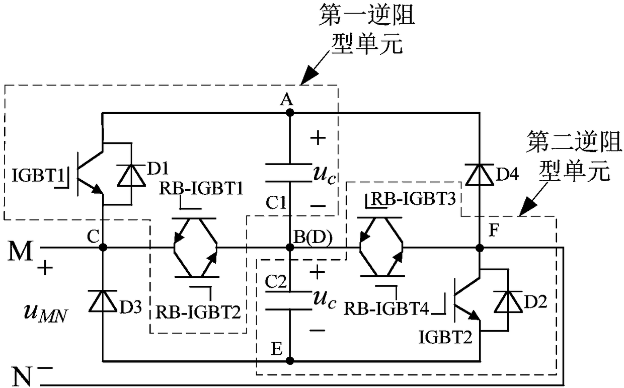
[0043] Embodiment 1 of the present invention provides a dual-resistance type sub-module, the structure diagram of which is as follows figure 1 as shown, figure 1 In A, B, C represent the first port, the second port and the third port of the first anti-resistance type unit, D, E, F respectively represent the first port, the second port and the third port of the second anti-resistance type unit Three ports, M and N represent the common point, specifically including the first anti-resistance type unit, the second anti-resistance type unit, the clamping diode D3 and the clamping diode D4; specifically, the first port of the first anti-resistance type unit A. The second port B and the third port C are respectively connected to the cathode of the clamping diode D4, the first port D of the second reverse resistance type unit and the common point M; the second port E of the second reverse resistance type unit is connected to the clamp The anode of the diode D3 and the third port F of...
Embodiment 2
[0053] Embodiment 2 of the present invention provides a control method for dual-reverse-resistance-type sub-modules. When the modular multilevel converter including the dual-reverse-resistance-type sub-modules is in the normal mode, the control method includes:
[0054] State 11): IGBT1 and IGBT2 are turned on and RB-IGBT1, RB-IGBT2, RB-IGBT3 and RB-IGBT4 are turned off, and the output voltage of the double reverse resistance sub-module is +2u c , u c Indicates the voltage of the energy storage capacitor in the first anti-resistance type unit or the second anti-resistance type unit;
[0055] State 12): IGBT1, RB-IGBT3 and RB-IGBT4 are on and RB-IGBT1, RB-IGBT2 and IGBT2 are off, or RB-IGBT1, RB-IGBT2 and IGBT2 are on and IGBT1, RB-IGBT3 and RB-IGBT4 turn off, the output voltage of the double reverse resistance sub-module is +u c ;
[0056] State 13): RB-IGBT1, RB-IGBT2, RB-IGBT3 and RB-IGBT4 are turned on and IGBT1 and IGBT2 are turned off, and the output voltage of the dou...
Embodiment 3
[0061] Embodiment 3 of the present invention provides a control method for a dual-reverse-resistance type sub-module. When the modular multilevel converter including the dual-resistance-resistance type sub-module is in a blocking mode, the control method includes:
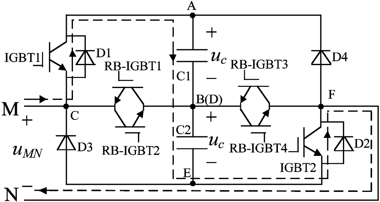
[0062] State 21): IGBT1, IGBT2, RB-IGBT1, RB-IGBT2, RB-IGBT3 and RB-IGBT4 are all off, and the current flow direction is from common point M to common point N (current flow direction is from common point M to common point N schematic diagram Such as figure 2 As shown), the output voltage of the double reverse resistance sub-module is +2u c , u c Indicates the voltage of the energy storage capacitor in the first anti-resistance type unit or the second anti-resistance type unit;
[0063] The current path is: common point M→diode D1→energy storage capacitor C1→energy storage capacitor C2→diode D2→common point N;
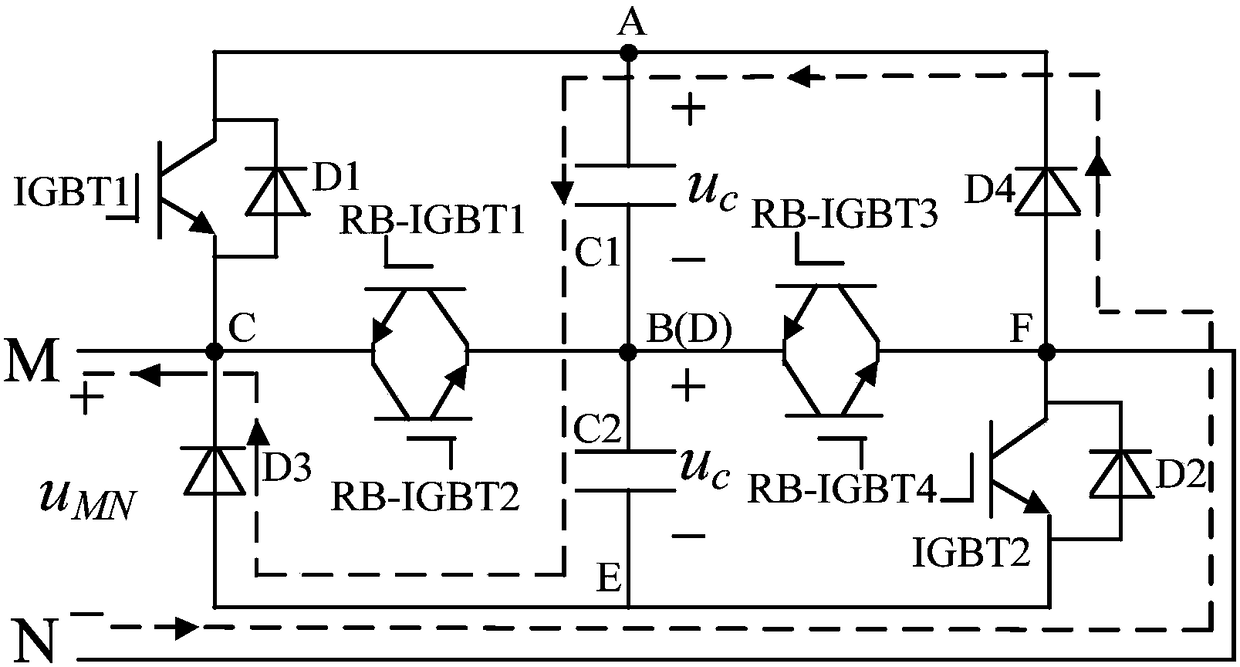
[0064] State 22): IGBT1, IGBT2, RB-IGBT1, RB-IGBT2, RB-IGBT3 and RB-IGBT4 are all off, and the curren...
PUM
 Abstract
Description
Claims
Application Information