Puncture device and anchor device

An anchoring device and anchoring technology, applied in the direction of puncture needles, human tubular structure devices, medical science, etc., can solve the problems of contralateral membrane or blood vessel wall height, membrane surface slipping, puncture needle puncture, etc. Achieve the effects of good puncture accuracy, high success rate and increased distance

Active Publication Date: 2018-08-14
ZHONGSHAN HOSPITAL FUDAN UNIV +1
View PDF8 Cites 7 Cited by
  • Summary
  • Abstract
  • Description
  • Claims
  • Application Information

AI Technical Summary

Problems solved by technology

[0003] However, the existing mechanical fenestration devices have the following defects: (1) When the puncture needle touches the covering film of the stent, due to the flexibility of the covering film, the covering film will sag toward the inside of the stent, which may cause the puncture needle to bend or fall on the surface of the film. Slipping; (2) When the film is depressed toward the insid

Method used


Image

  • Puncture device and anchor device
  • Puncture device and anchor device
  • Puncture device and anchor device

Examples


Embodiment Construction

[0042]In order to make the object, technical solution and advantages of the present invention clearer, the present invention will be further described in detail below in conjunction with the accompanying drawings and embodiments. It should be understood that the specific embodiments described here are only used to explain the present invention, not to limit the present invention.

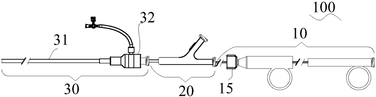
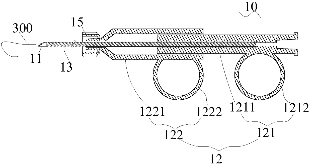
[0043] In order to describe the structure of the puncture device more clearly, the terms "proximal end" and "distal end" are defined here as commonly used terms in the field of interventional medicine. Specifically, "distal end" means the end far away from the operator during the surgical operation, and "near end" means the end close to the operator during the surgical operation.

[0044] Unless otherwise defined, all technical and scientific terms used in the present invention have the same meaning as commonly understood by one of ordinary skill in the technical field of the present invention. The...


PUM

PropertyMeasurementUnit
Axial lengthaaaaaaaaaa
Lengthaaaaaaaaaa

Abstract

The invention discloses a puncture device, which comprises a puncture needle, an expandable anchor balloon and a catheter. The catheter penetrates a near end and a far end of the anchor balloon, and the puncture needle is movably stored in the catheter. In a full state, a center area of the far end of the anchor balloon is recessed towards the near end to form a recessed area, and a far end of thecatheter is positioned in the recessed area. The invention further discloses an anchor device which comprises the anchor balloon and the catheter. By the puncture device, puncture accuracy is improved while the puncture success rate is increased, and after finishing of puncture, an expanding balloon can be conveyed along a guide wire to expand a puncture port only by retreating of the puncture needle and a push rod. In addition, since a far end of an anchor component is abutted against a punctured area, the probability that the puncture needle continues moving forwards to puncture opposite tectorial membrane or blood vessel wall after success of puncturing is decreased.

Description


Claims


Application Information

Patent Timeline
Owner ZHONGSHAN HOSPITAL FUDAN UNIV
Why Eureka
Try Eureka